Description
Introduction
So one of my friends gave me a box or boxes of old goodies, or toys as I like to call it all. In it I found an old Ford Probe Audio Amplifier. First thing that comes to mind is “does it even work?”. So it was time to find the pinout tables or at least the wiring guide for the device. After my friend found the diagram I was less than impressed. Not only did the wires for the plugs I had not match the ones on the diagram, but the numbers on the pins on the two black connectors it had didn’t even come close to matching up.
Does it even work?
Using a bit of modder’s intuition I was able to figure out the power input lines. It was quite obvious since they were ran to a rectifier type coil to cut out alternator whine (or electrical hum from the power system). But that was not every bit of info I needed to even turn it on. Anyone who has installed an amp in their car will remember the “amp on” line that triggers the unit to turn on. Since in most cases thick wire is run to the Battery+ and ground lines it is far easier to turn it on with another line to provide power. I figured that would be close to the power input, turns out I was right on that.
Since it would not be going in a car or in that type of environment again I just soldered the “amp on” line directly to the +12v input. I could change that later to actually be used, but for now its of no issue. Next I had to guess and check mostly for 8 wires on either connector for the 4 speaker outputs and the 4 audio inputs. A little volt metering and an hour or so later I had all the info I needed. Desoldering the silly plugs it had so I can put my own more useful headers on it.
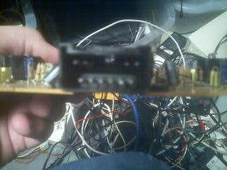
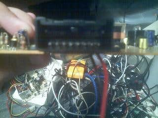
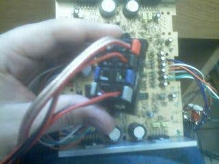
Those were the connectors previously on the board to interface it to the car.
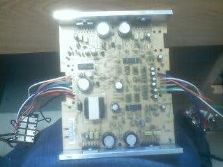
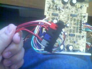
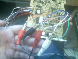
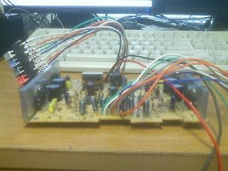
The board with its new wires soldered on and the 4 speaker header I saved from an old audio amp that got fried.
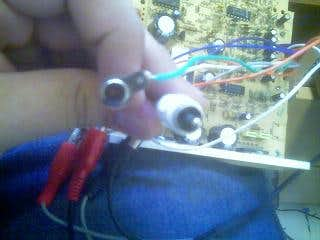
The speaker header and the 4 RCA bolt on plugs I got from RadioShack.
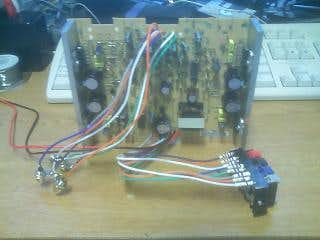
And the unit all hooked up to the little 12v battery I had handy.
Adding Connectors
Utilizing some of the old parts to its case to make the new case and to measure up the new parts I will cut. The two large heatsink side pieces will stay just how they are, I want this to be passively cooled so it creates no noise, also it gives it that neat look that the sides would otherwise look a bit too bare.
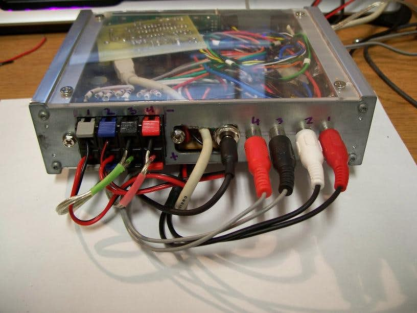
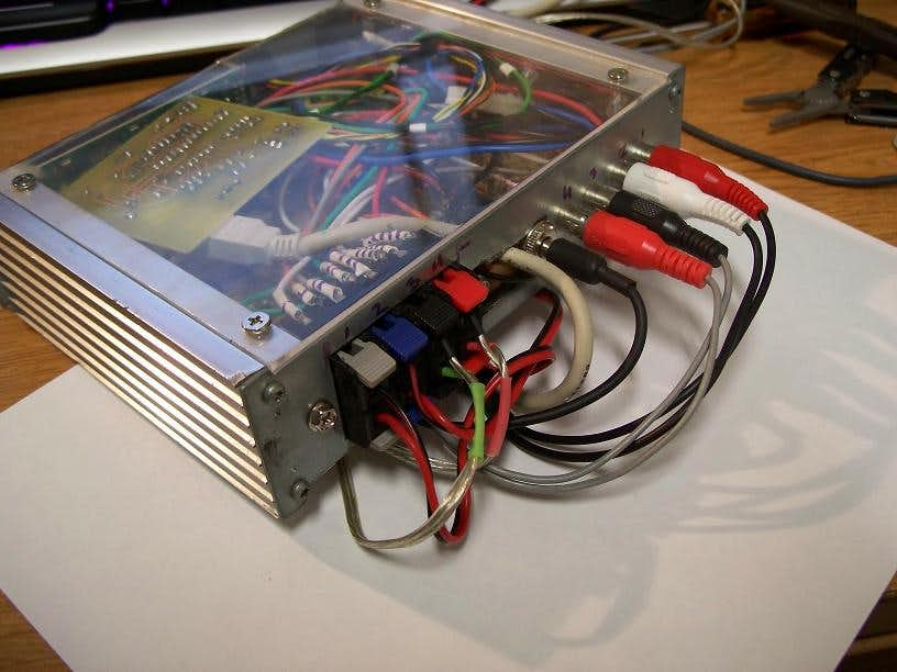
Also making the choice to have all the plugs on the back, one thing I cannot stand is for plugs to go in more than one end of a device. So the back will have the speaker outputs, the audio inputs, and the power input. For this particular device I will make it externally powered. This is for two reasons. 1) To attempt to cut down on any electrical noise that would interfere with good audio 2) To keep the unit I have to look at much smaller and the power brick can be somewhere else. It also gives me several options for powering it as it takes a very standard 12v input.
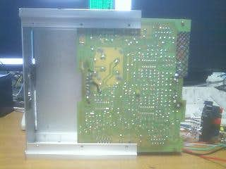
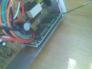
Just some pictures of the current amp board, as well where I have marked on the white heat shrink which audio input line goes with what speaker output. The audio jacks are also labeled on the wire. For my own benefit.
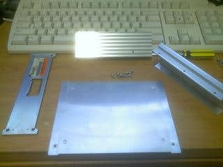
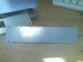
Some parts of the original case, the two large side heatsinks, and one of the front/back pieces that I am using to hold it together and to make new ones.
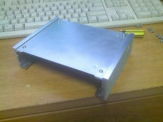
The case taking shape and one of the top plates that were originally on there, Not sure if I will end up using it either.
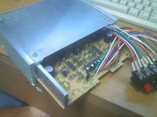
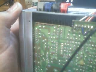
Sliding in the amp board into the heatsink case assembly.
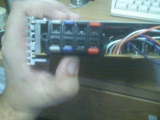
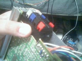
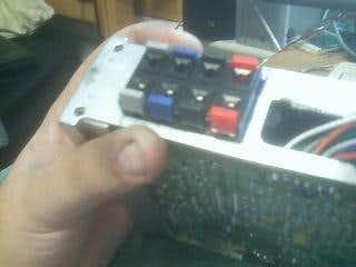
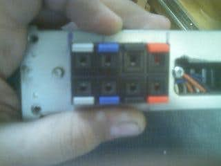
This shows the speaker output assembly, which will require me to cut away part of the amp board and relocate a few components and traces to fit inside the case. It is either this or make the case much larger and fuglier. I choose the solder a little bit route.
This is the little bolt on barrel jack that I will be using, it is from RadioShack. I Use this size of barrel plug all over. I have many devices that use 12v and this size jack. My way of making things more modular.
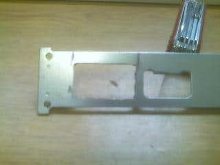
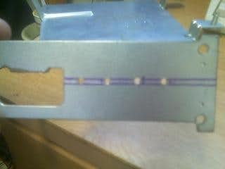
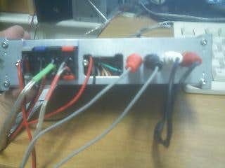
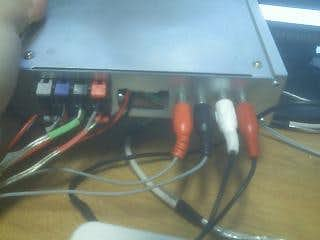
Just a shot of the audio jacks, and the front/back piece of the amp, showing how thin and small it is.
Cutting holes and PCBs
I decided to go ahead and cut out the spot on the amp’s board and relocate the component that was originally in that spot.
Image showing the speaker header now in the same spot where I cut the spot out on the pcb and the capacitor i relocated.
More pictures of the same, more angles of the cutout and how it will fit in there now without having to make the case much bigger. If it were not for the gaping hole in the middle of the back plate I would be inclined to keep the plate as is. But since I am getting good metal for this project I decided to mess up all I wanted to on the original piece and get all the measurements right for a new cut on the final pieces.
Some rough first cuts with the Dremel, and then the connector finally in the hole.
Pic showing the reason I had to cut part of the PCB, and the header mounted with screws.
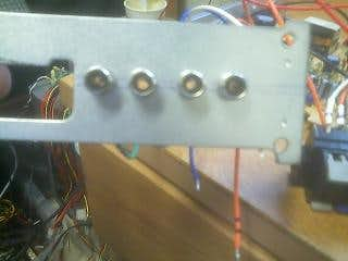
The little bolt on RCA jacks and the pilot holes for them.
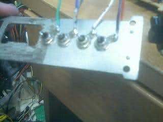
RCA jacks all mounted and soldered up.
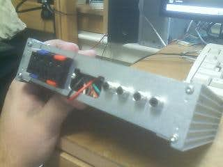
The unit all completed in mock-up form, minus the power plug since there is no room to mount it due to the … gaping hole.
The amp all plugged in and playing my music YAY!
Adding an LCD
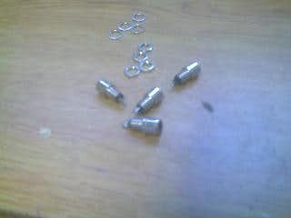
I went ahead and cut a hole for the little character lcd to fit through. Just for now its held in with a bit of tape, I have some metal standoffs and screws I will probably use to bolt it on there more permanently. It is hooked up via parallel for the time being. Looking for a good solution to interface it with USB. Perhaps I will do ch424’s PIC controller.
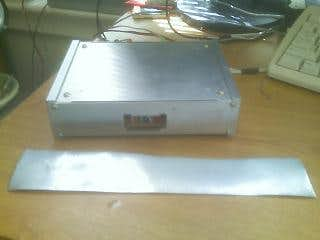
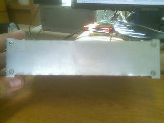
Using a piece of scrap sheet metal I made a mockup front piece to put on the Amp and serve as a template for cutting a nicer piece of metal.
With the new piece bolted in place I sized up for a small lcd.
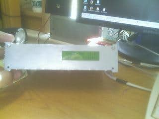
I then cut a rough spot for it to poke through, and brought it to life.
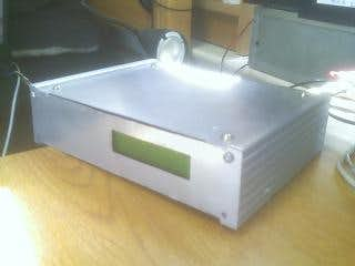
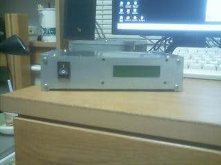
Just two action shots of the lcd on and the amp all bolted together.
I was thinking it may be nice to have a switch to turn the unit on and off. So since it is still in the mock-up phase I went ahead and cut a small hole for the power toggle to poke through.
Adding a window and lights
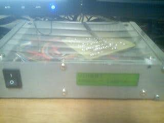
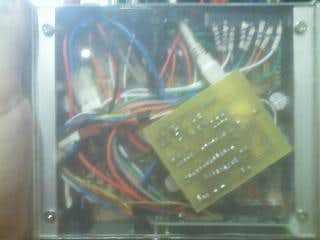
I have also decided to cut a mock-up plexyglass top plate to the amp just to see how I like the looks of it having a clear lid. I cut the plexy from the clear diffuser plastic from the back of a busted laptop panel. It is not a terribly nice plate or nice cuts I preformed on it, but it will do well for demonstration moving towards completion.
I also added some internal lighting by using 8 super-bright LED’s that I desoldered from a old car’s brake light bar. I have the led’s under volted just a little bit to prevent damage and also because I do not need it to be really bright, just to be clear and diffuse well.
The newly added clear top to the amp, note the LCD has been removed awaiting its usb controller counterpart.
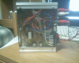
Just two more shots and showing all the cables plugged into it as current.
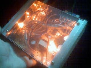
Pic of the LED’s all turned on. Trust me this looks way better in person my terrible camera does not do it justice, this is also a rich red and not orange or pink.
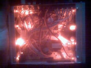
Of course no light job is complete without some dark shots of it lit up, yet again this looks quite impressive in the dark.
Adding USB to front LCD
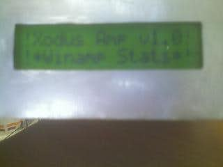
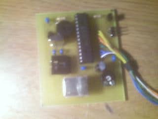
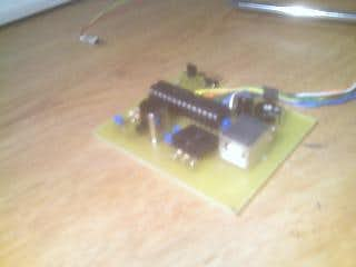
I have installed the USB lcd controller from ch424 and configured a few screens through LCD Smartie.
Step 1
Build the controller per ch424’s diagram and code located in the mod guide here: Make your own USB LCD controller!. Then install the drivers to connect it to windows.
Step 2
Install and configure LCD Smartie per what you want it to display. In my case a Winamp spectrum analyzer. Also grab the plugin for Winamp and install that per the instructions.
It is fairly explanatory from there on, just configure things how you want it to be.
Currently just a temporary setup of the driver board and the usb plug, Soon I will put the usb port on the back of the amp so it can be unplugged rather easily. but for now in the testing phases it works just fine.
I have LCD Smartie so that when Winamp is playing it displays the spectrum analyzer with the song title scrolling at the bottom.
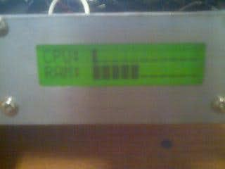
When Winamp is paused it blinks the word paused with the song title scrolling. when Winamp is off or stopped i have it display cpu and ram usage graphs.
