Description
Introduction
While most of this information can be found online I could not find a central source of all the necessary information specifically as it applies to the ex495 series.
Finished Project
The desired outcome of this project is that you should be able to access the BIOS of the HP ex495 and interact with the installed operating system using a USB keyboard and mouse.

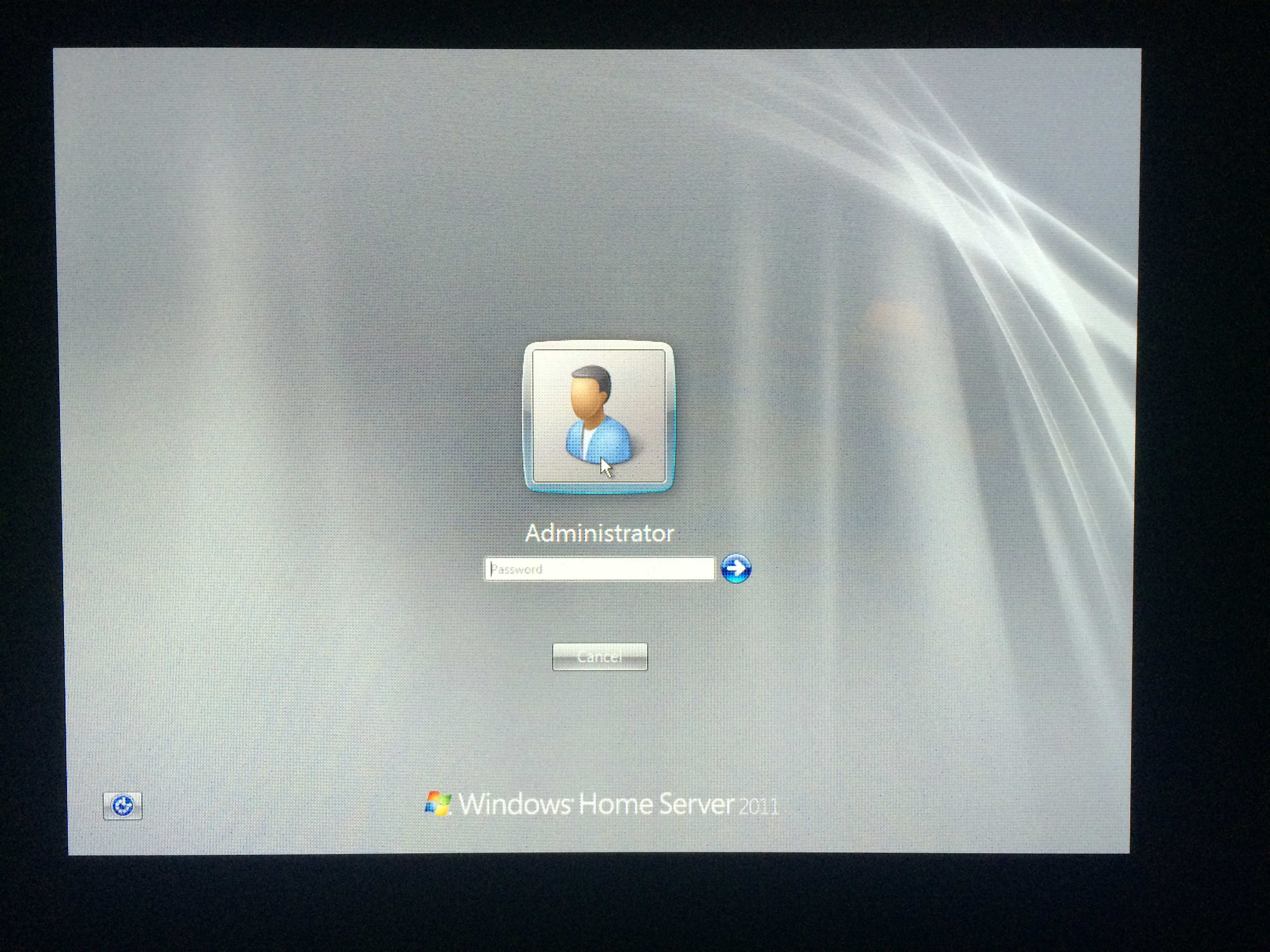
Here we have the main BIOS screen, this one is actually quite extensive with fine grain control over fan speeds and hardware configurations. It is likely that many more options are present since HP never intended the general public to access this console. Lastly I finally get to see the login screen Windows has been trying to show me all along.
Cracking The Case
Don’t bother with taking the base off it doesn’t gain access to the unit but for those that have to take things into every party they come (myself) go right ahead. Remove the top, the right side and the rear panel. These have clips that can be accessed from the inside when the drives have been removed that lets them slide backward (top and side) and upward (rear).
This part is admittedly difficult and during the process I broke every single clip thinking they were of the pressure variety. These however actually hold on until pushed. Nothing a bit of super glue couldn’t fix and honestly it was a lot more fun to remove them with force anyway.
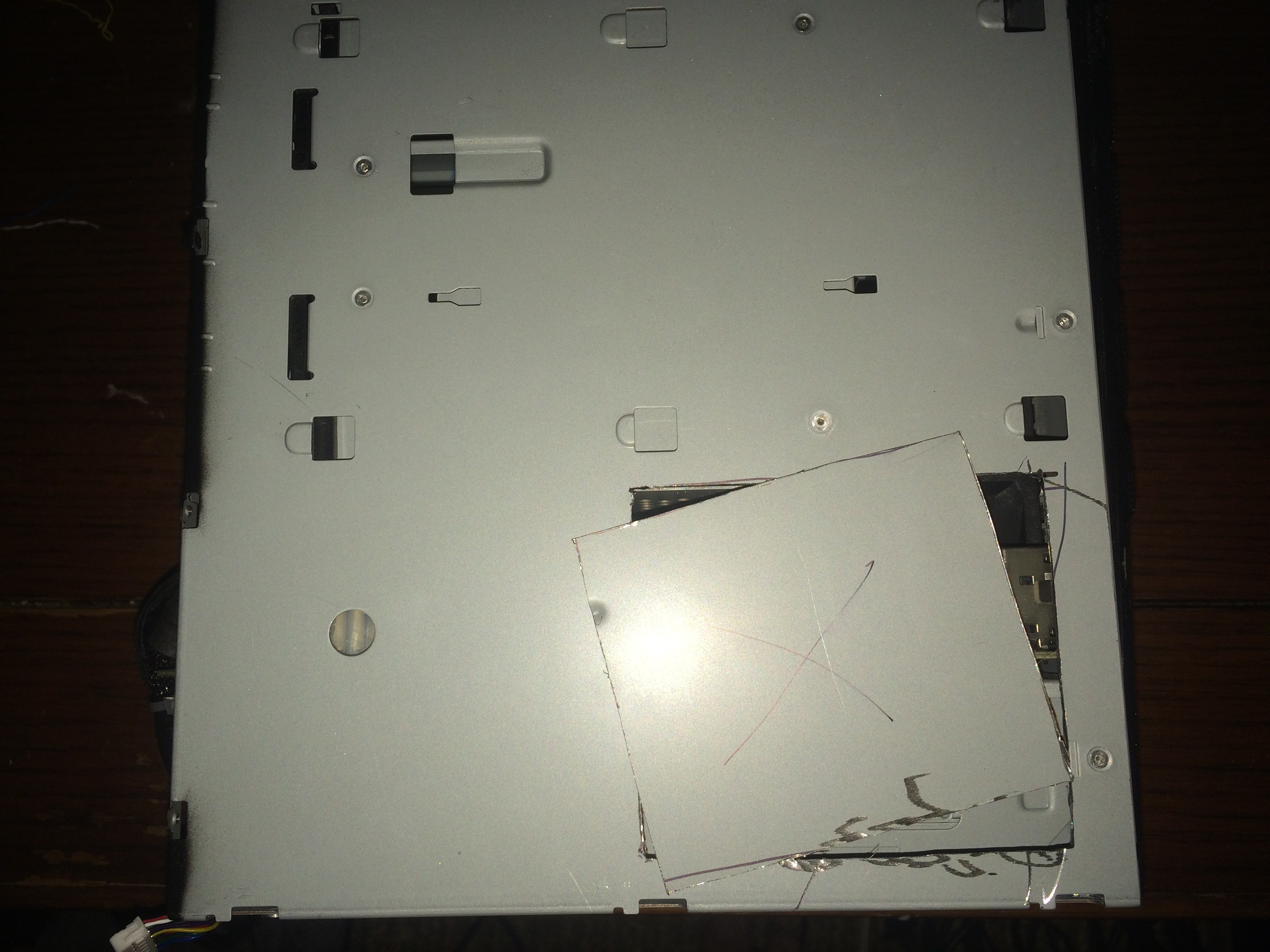
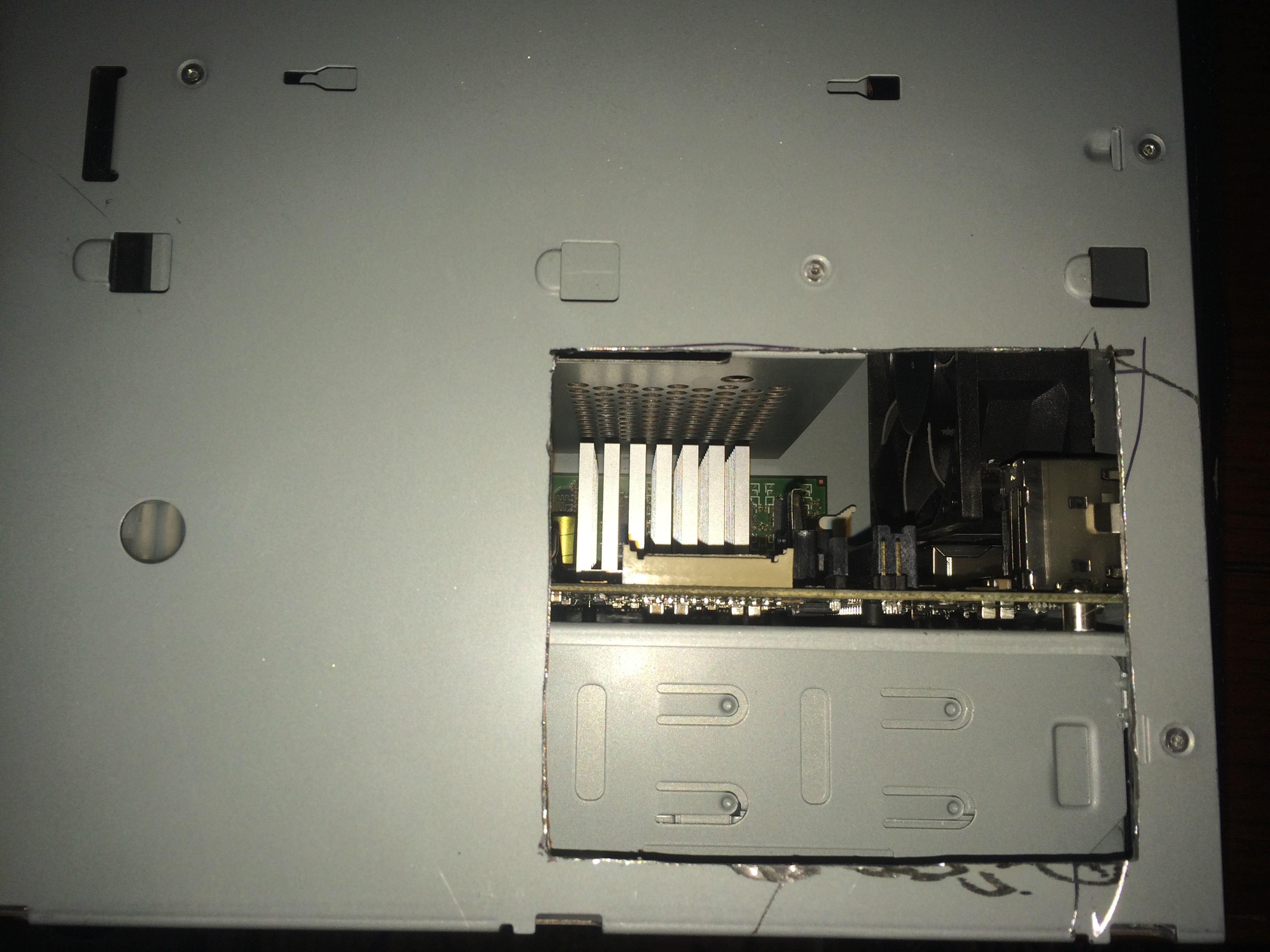
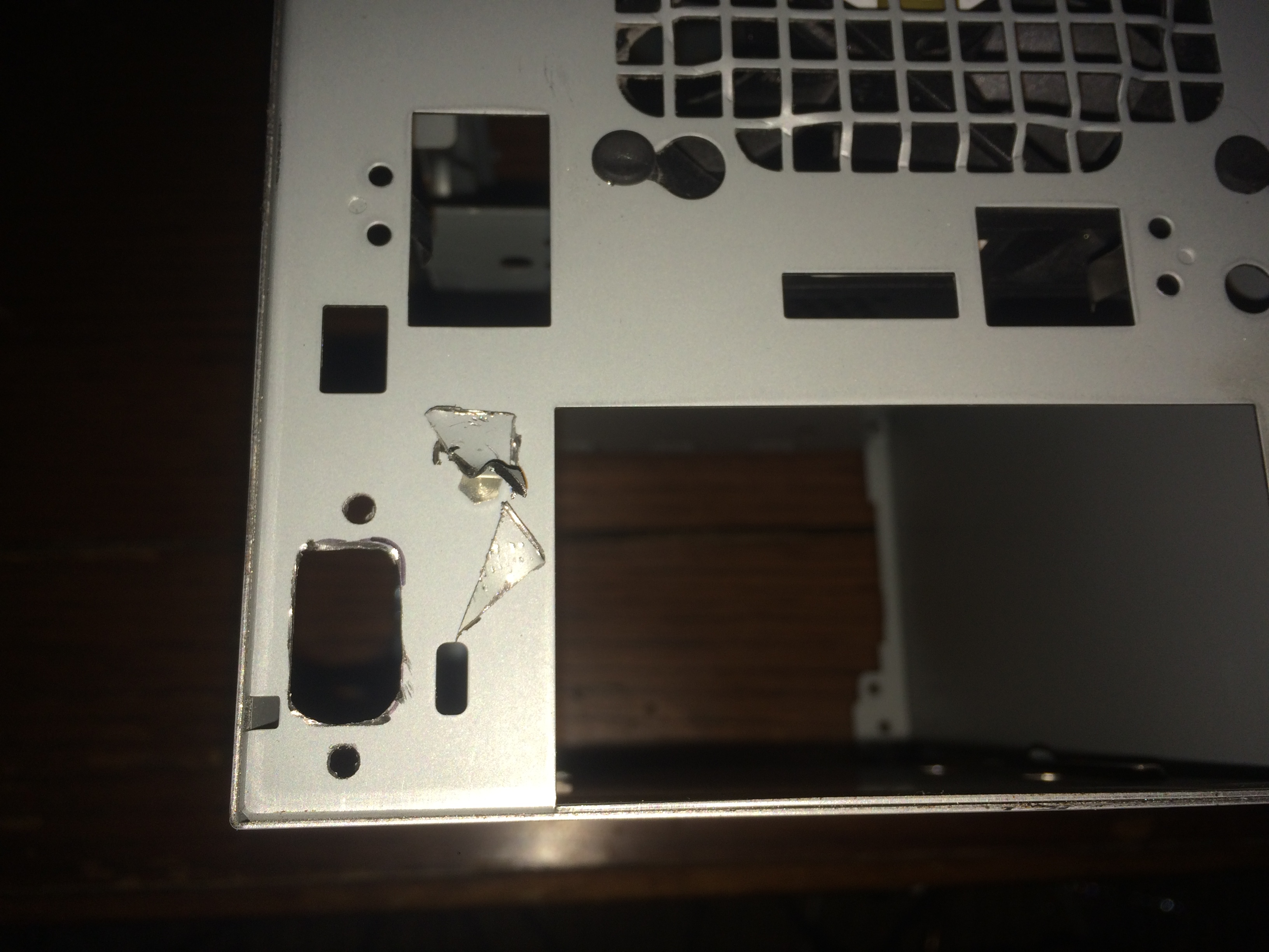
Evaluation and debug versions of the media smart servers actually have a punch-out allowing easy access to the magical header in the below pictures. After seeing this I decided to cut a hole in the same place slightly larger that would make installing the resulting VGA port much easier as well. This area is completely covered by the right panel so the cut can be a bit rough, just make sure to sand off any sharp edges.
VGA Cable and Pinout
The pinout of the magical connector is well known and connected as described would probably work but chances are that if you are the type of person (me) who sees 6 ground pins and connects half then pay attention to the second diagram.
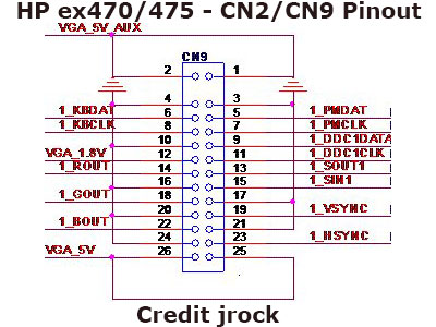
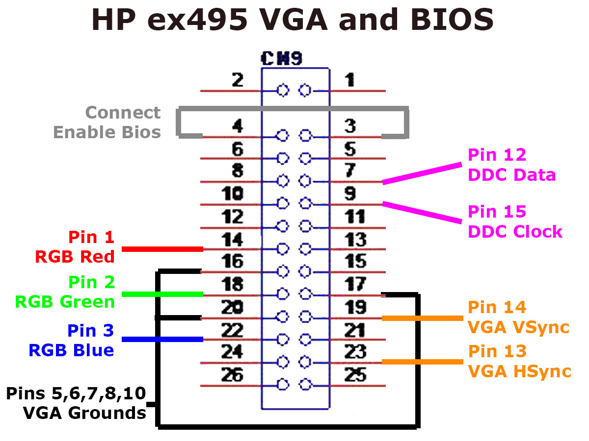
The first diagram leads you to believe that there are 6 ground pins on the connector however what it is really stating is that all 6 of those pins should be connected together and then be treated as a single ground collectively. Pin 4 actually is an enable signal of sorts and needs to be connected to a ground or Pin 3 since its closest. The rest of the grounds can be taken from the pins shown in either the first or second diagram. The second diagram being my eventual connection that worked for me.
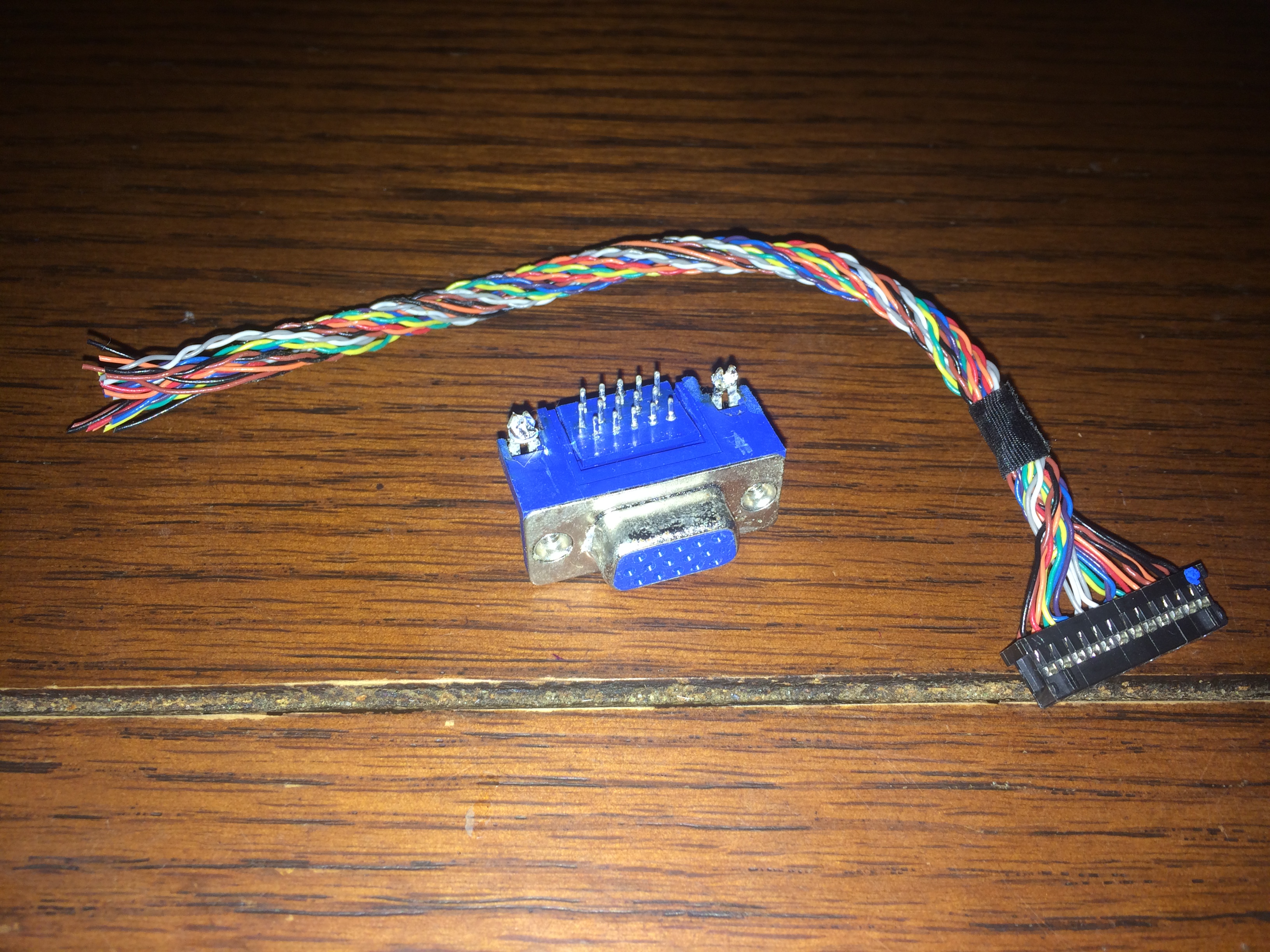
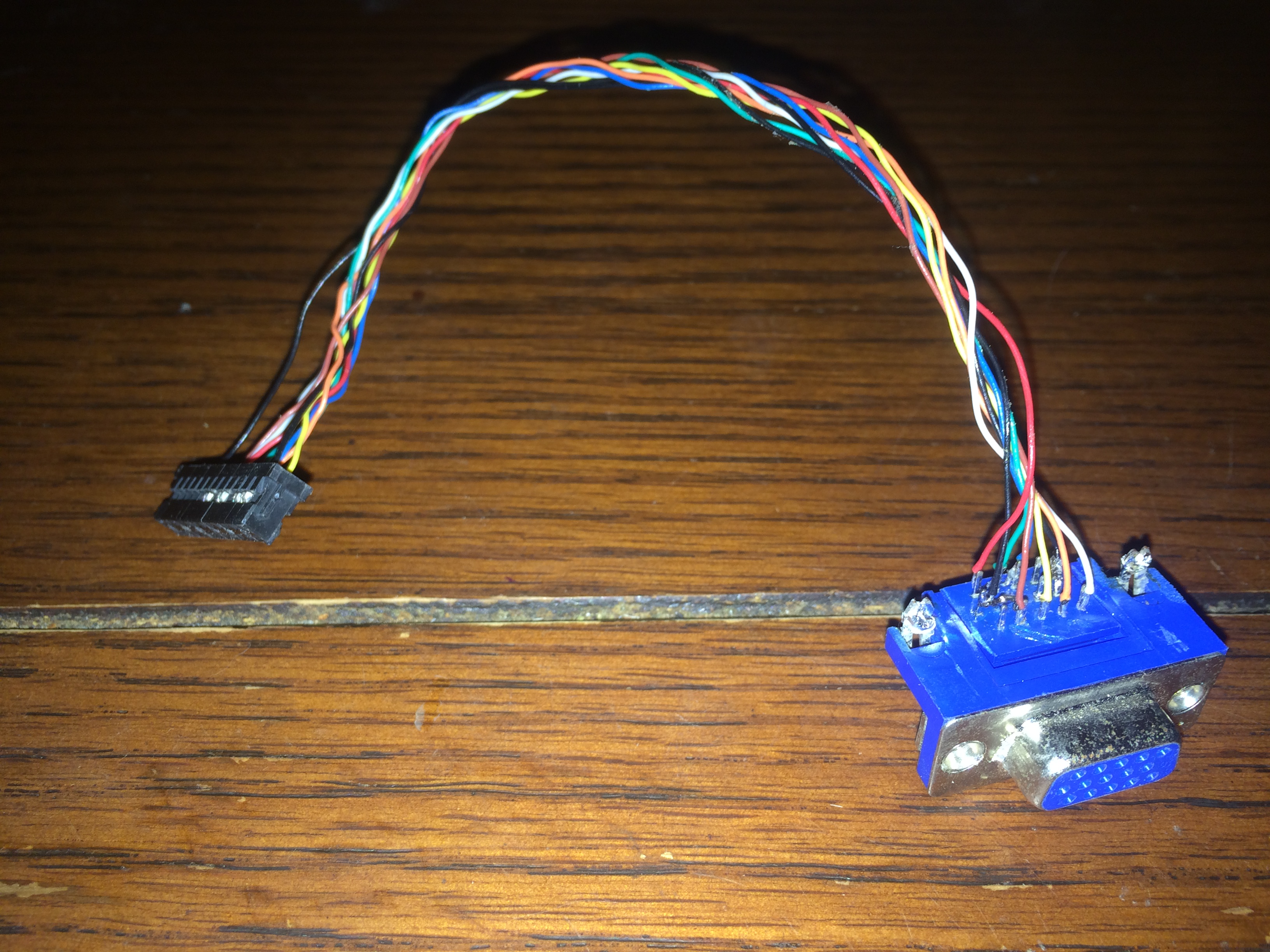
Next it was time to construct a cable to fit the magical connector. On a whim I was able to find 3 separate cables in my parts bin that fit this connector and had wires already attached. The nice thing is that most of these connectors allow you to remove the pins so I even had the opportunity to use a red wire for the rgb red signal and a green wire for.. you get the idea. If you don’t have one of these laying around use the links at the bottom of the page to get the appropriate parts from digi-key or your parts supplier of choice. Intrepid users could solder directly to the pins on the motherboard and while this isn’t recommended these units have reached a particular age that all warranties are expired and maybe you want to mod on the cheap.
Wrapping it all up
Using the space that is unoccupied by the power supply we can add the VGA connector in the lower left hand corner of the rear of the ex495. Pin 1 of the connector is closest to the front of the unit and lastly connect a jumper to the pins circled in the first image below. This was necessary in addition to the diagrams above to properly enable the interactive BIOS.
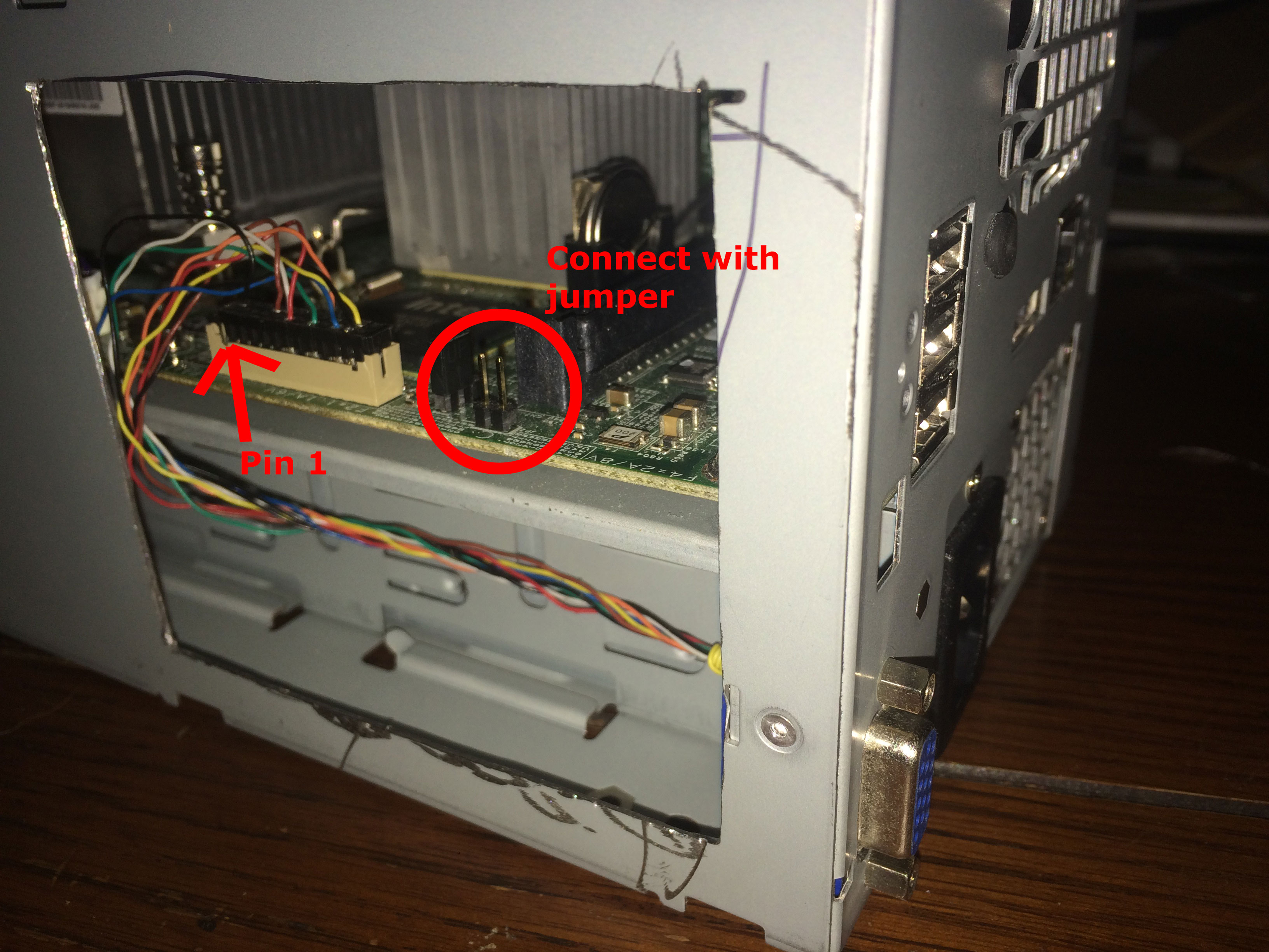
Place the VGA connector in the lower left hand corner, make sure the power supply does not get blocked, including the little tab on the sliding frame.

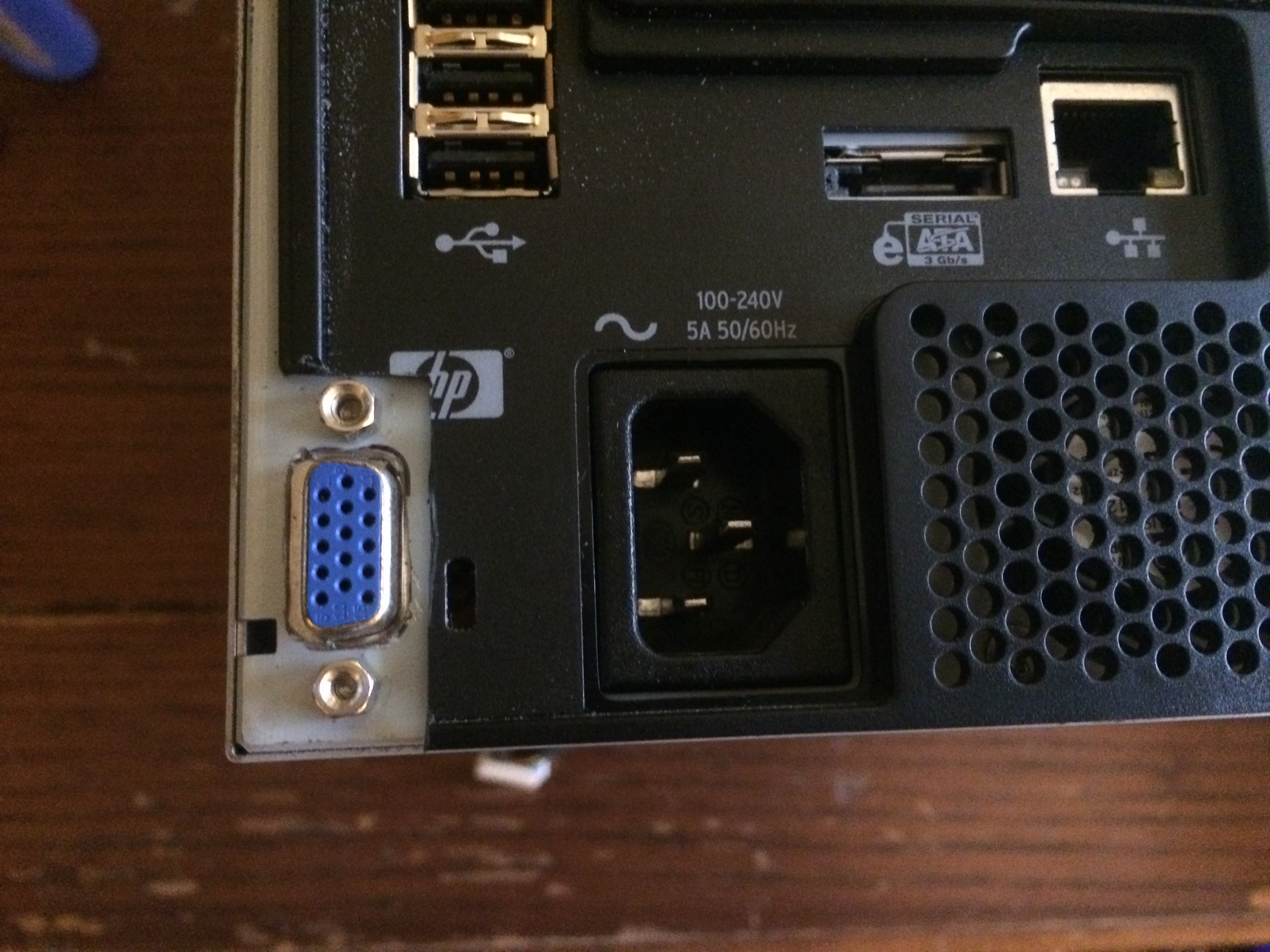
Lastly make a cut in the rear panel to expose the new VGA port, you could probably make the cut a bit more professional looking but the looks of the rear of this particular device aren’t all that important at least for me so there you have it. Button up the ex495 and enjoy your new VGA connection. Use a USB keyboard and mouse and hit DEL during the POST to access the BIOS itself.
Troubleshooting
If you can’t get the BIOS or boot order options to work then either the jumper is missing or pins 3 and 4 were not connected together. If you haven’t already, go ahead and connect all of the pins in the first diagram indicated as grounds together, and make triple sure you have the connector hooked up the right way.
Parts
- 26 position 2mm pitch Connector Housing
- 24-28AWG Crimp Connectors
- Female 15 Position D-Sub Connector Receptacle