Description
The goal of this project is to create a monitor containing a hidden image that can only be seen under certain conditions like the scavenger hunt monitors at Google I/O.
Introduction
Unfortunately while the great Google bot in the cloud did not grace me with an invitation to I/O 2015, a co-worker of mine attended and while all of the presentations are filmed and available on Youtube, one thing really peaked my interest though that is not mentioned anywhere I can find online.
Google being fueled by pure nerd awesomeness apparently runs some sort of geeky scavenger hunt during each conference. This year (2015) Google gave out a lanyard, seen in the video below. This lanyard is actually a piece of polarizing plastic and when turned at different angles will either block out entirely or let through the light from an LCD. Using this lanyard it was possible to read information off of specially crafted displays at Google I/O.
Concept
With no official information and only accounts of the effect at play it was time to take a stab at recreating this for myself. In concept an LCD uses a piece of polarizing film on the front and back rotated at 90 degrees to the other. When pixels show a color they selectively twist or untwist light as it travels through the glass. The polarizing sheet in front blocks out light that is not polarized in a certain way, removing the front sheet from a typical monitor makes the image completely white since the human eye does not see a difference in the orientation of light waves.
In theory it would be possible to take a second LCD without polarizing sheets and place it in front of a normal LCD and create a device where the image on the LCD in front is invisible until viewed through a polarizer at a particular angle.
Completed Project
A demonstration using the actual badge from Google I/O and also one of the polarizing sheets taken from the monitor during deconstruction. There is a slight transflective effect made much worse by trying to take a video of the monitor in action. This is likely caused by a difference in the pixels between both monitors and also not being perfectly aligned.
Files used in the making of this demonstration can be Found Here.
Two Panels Enter
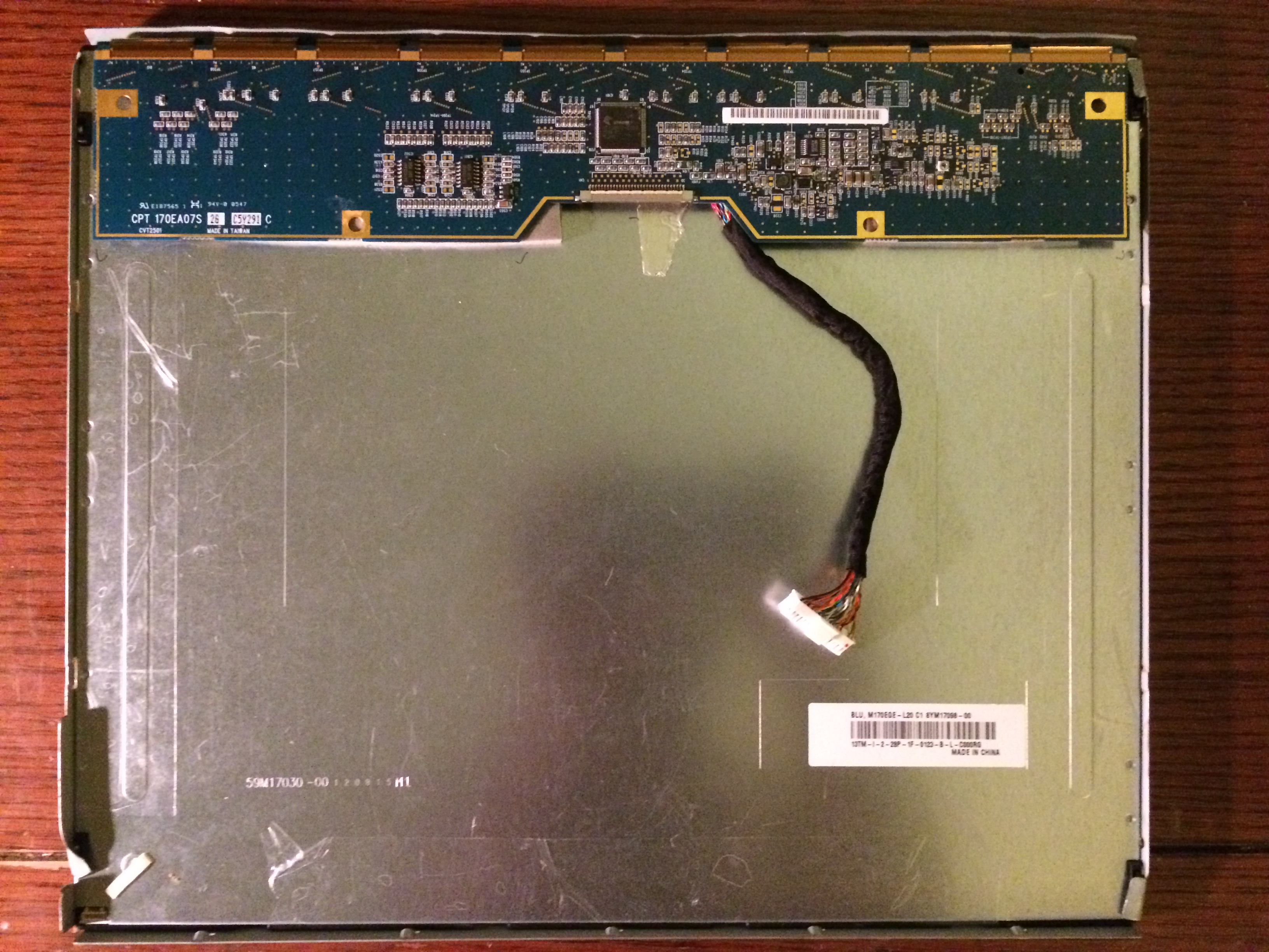
First we start with two LCD panels with the same dimensions and resolution.
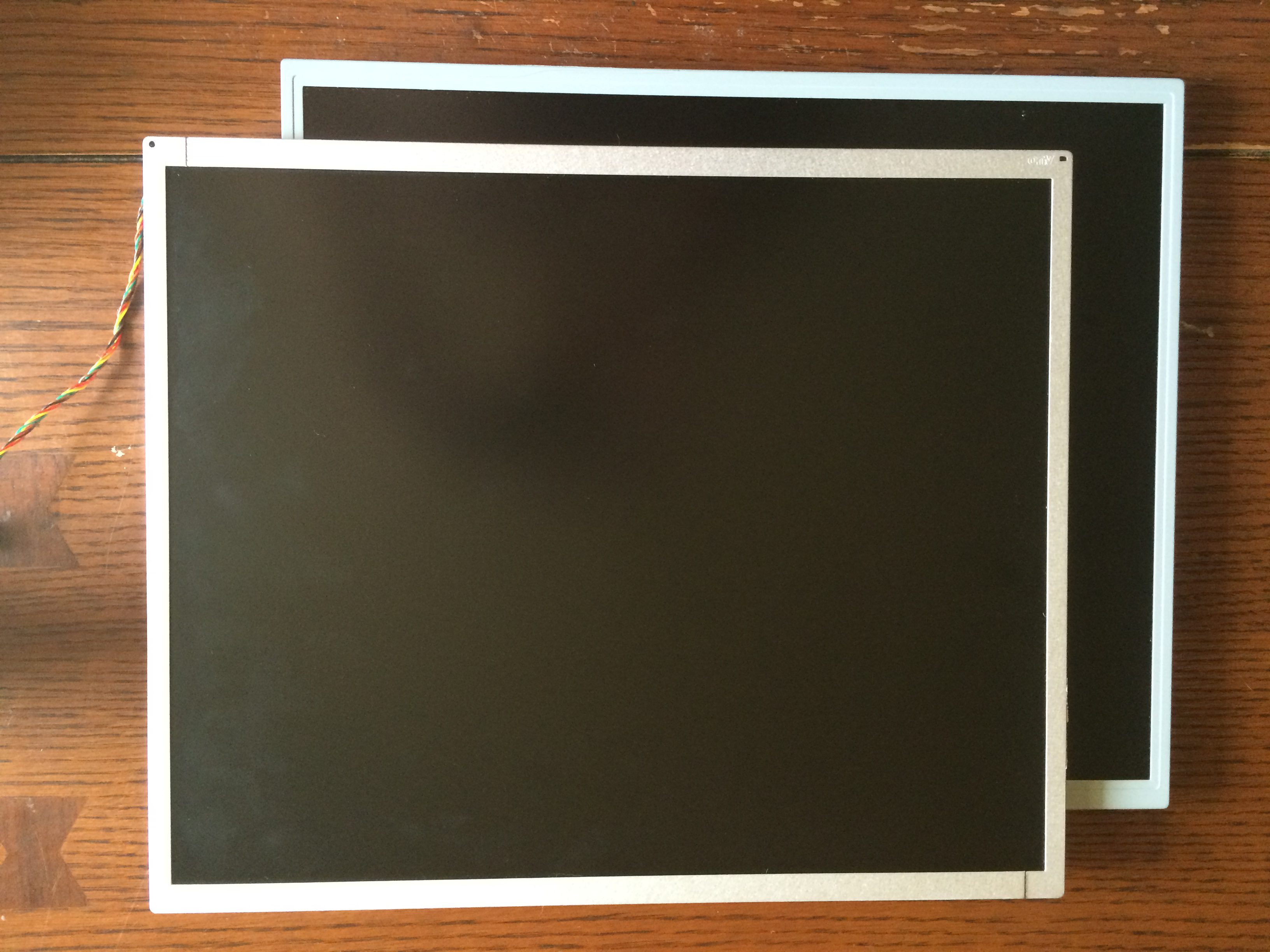
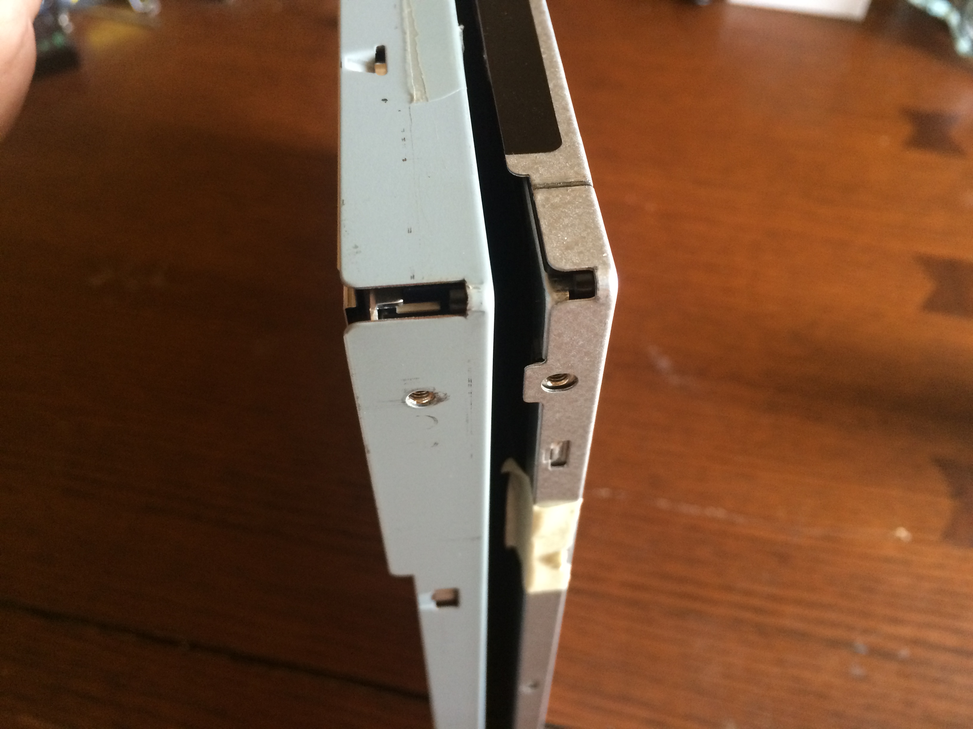
The thicker of the two panels is an older version that still uses cold cathode backlighting. The thinner panel is an LED backlit version that is also much brighter than the cold cathode one.
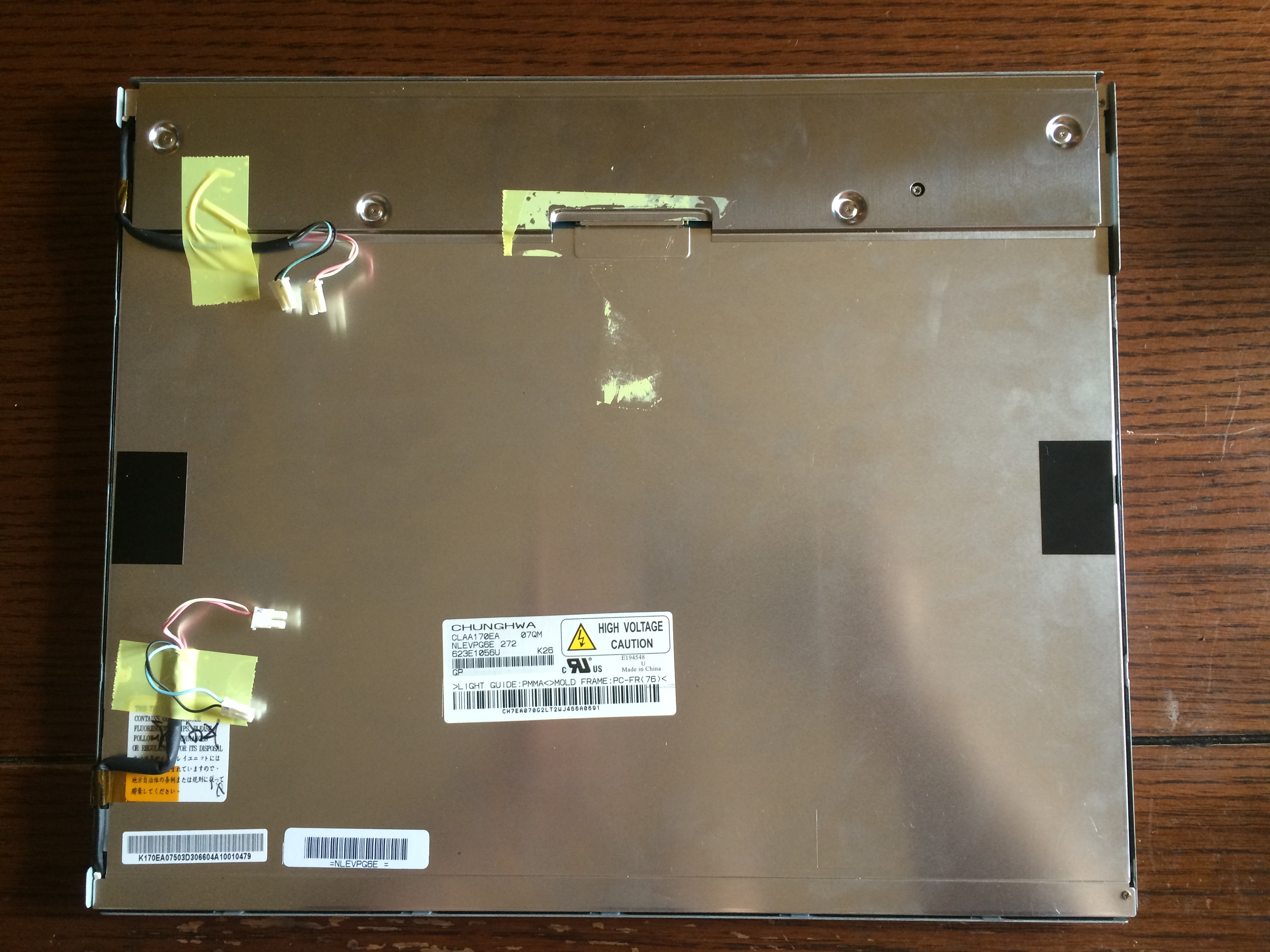
Front Panel
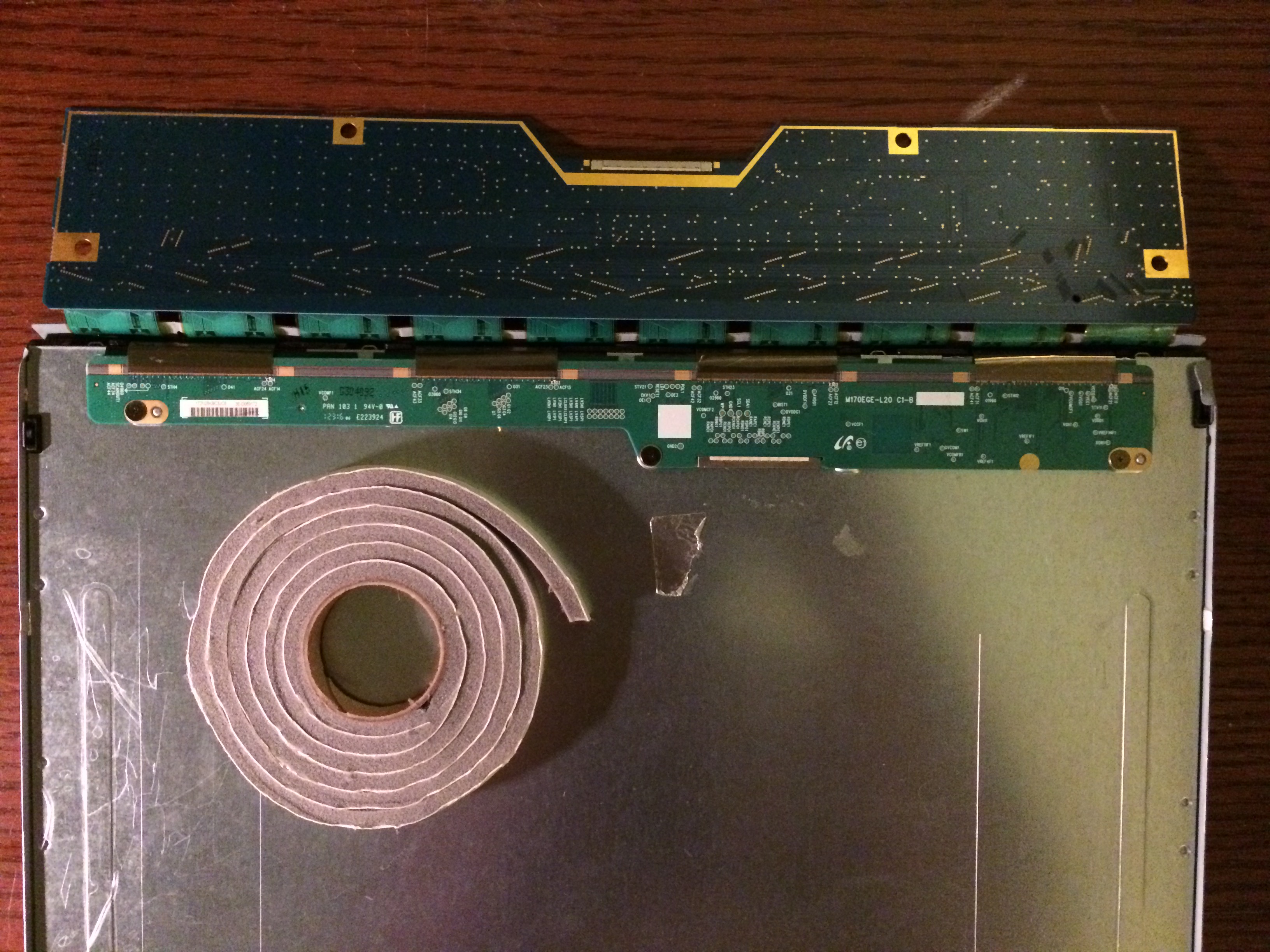
The front panel being slightly thicker than the LED version has longer ribbons attaching the controller board to the LCD glass itself. This makes it easy to place this LCD in front of the second and still have enough cable to place the board in the rear of the panel assembly.
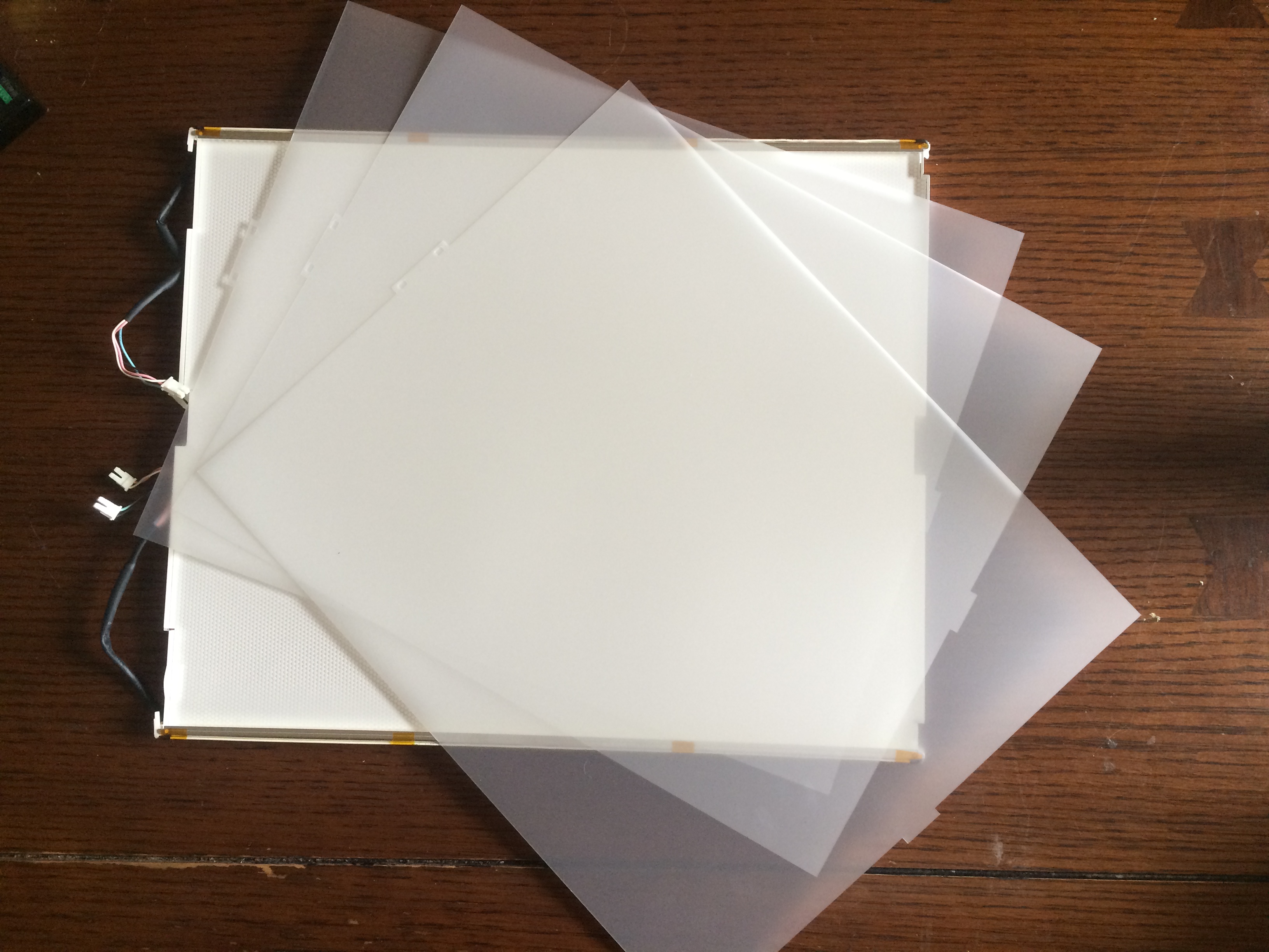
First the panel is stripped down and all the unnecessary bits removed including the backlight, diffuser sheets, and the frame.
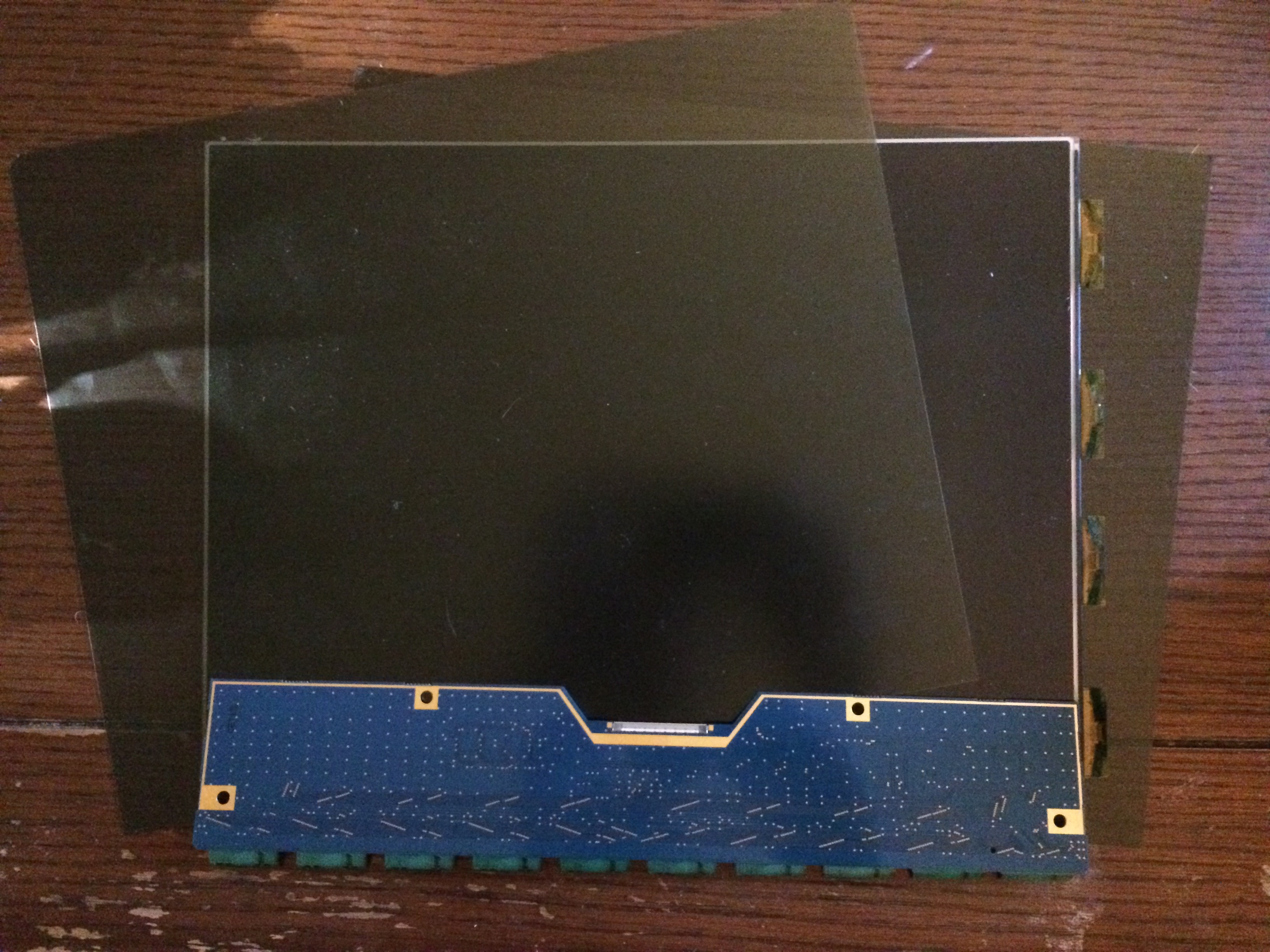
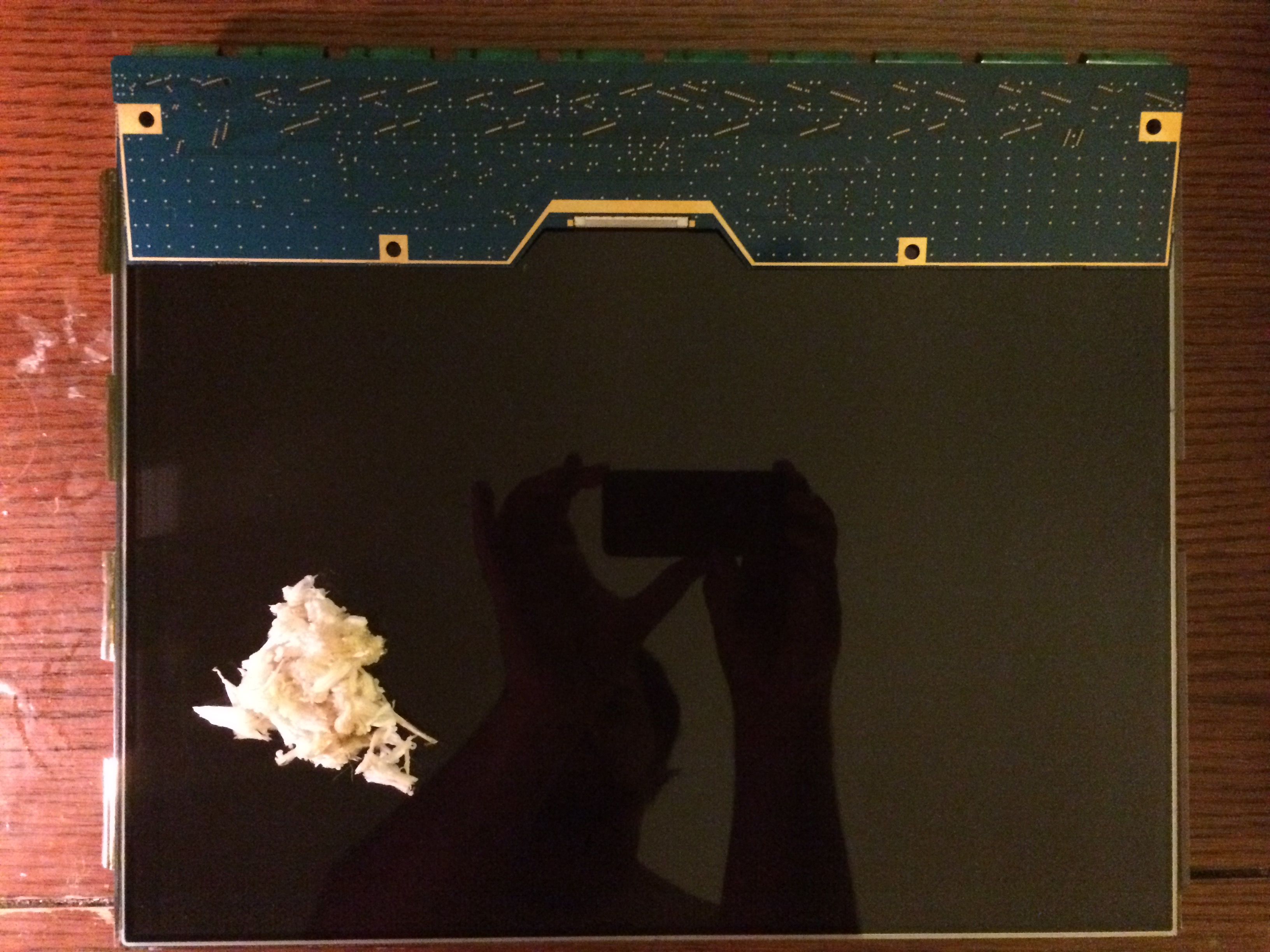
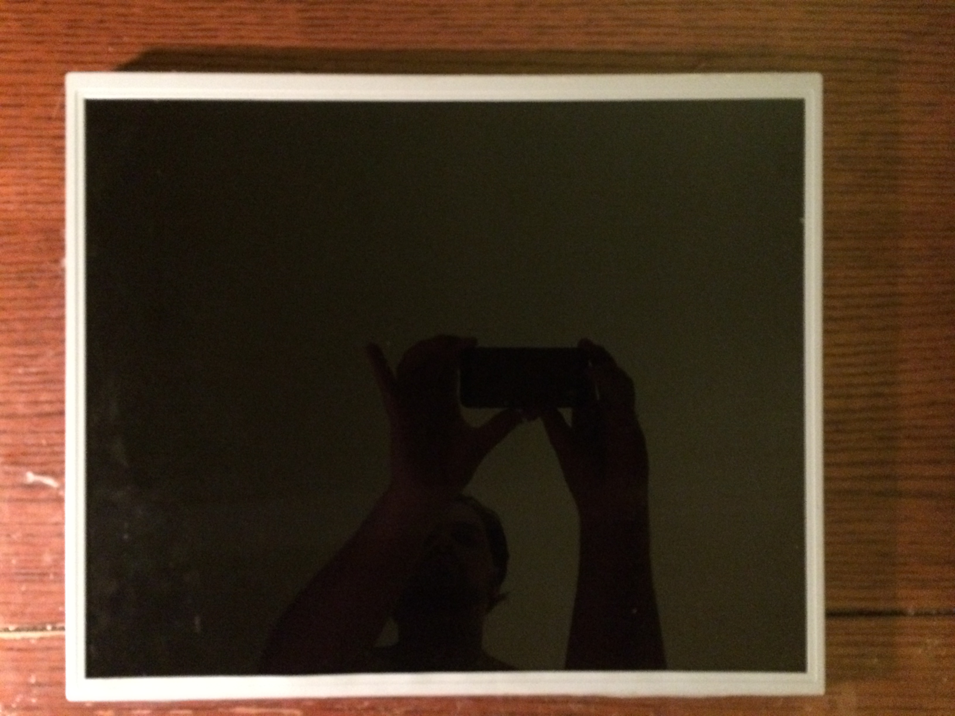
Next the polarizing sheets that are glued to the front and back of the LCD are removed. This process can be very difficult and time consuming. With the sheets removed the glue and residue must also be removed. Thankfully a utility blade at a 30 degree angle makes this part easy. Lastly a Dremel buffing wheel was used to remove the remaining bits and clean the LCD to a perfect shine.

Now the front LCD is ready to attach with the rear LCD. Using the thicker frame from the CCFL backlit panel the front LCD is placed, aligned, and taped in place. Next the double LCD assembly is placed in the frame. Since the assembly is still thinner than the old CCFL version and the tabs don’t line up the corners are bent over to hold the whole assembly in the frame.
Lastly the controller board for the front LCD is attached using some double sided foam tape. Unfortunately the controller for the front LCD is much bigger and covers the controller for the rear LCD. This isn’t much of an issue though as the foam tape can be easily unstuck to attach the cable and really only needs to happen once or twice as the panel assembly is installed back into the original monitor housing.
The Controllers
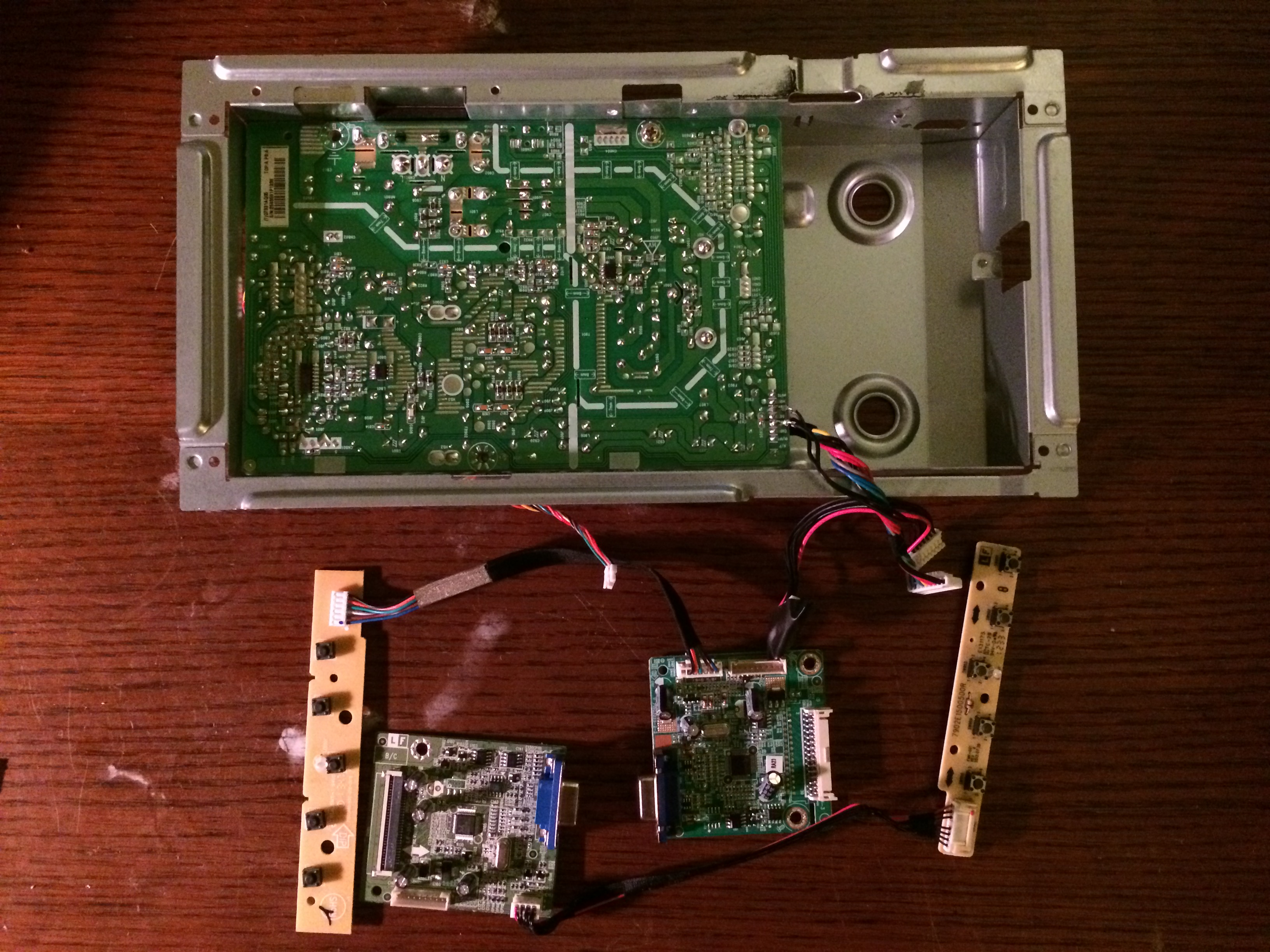
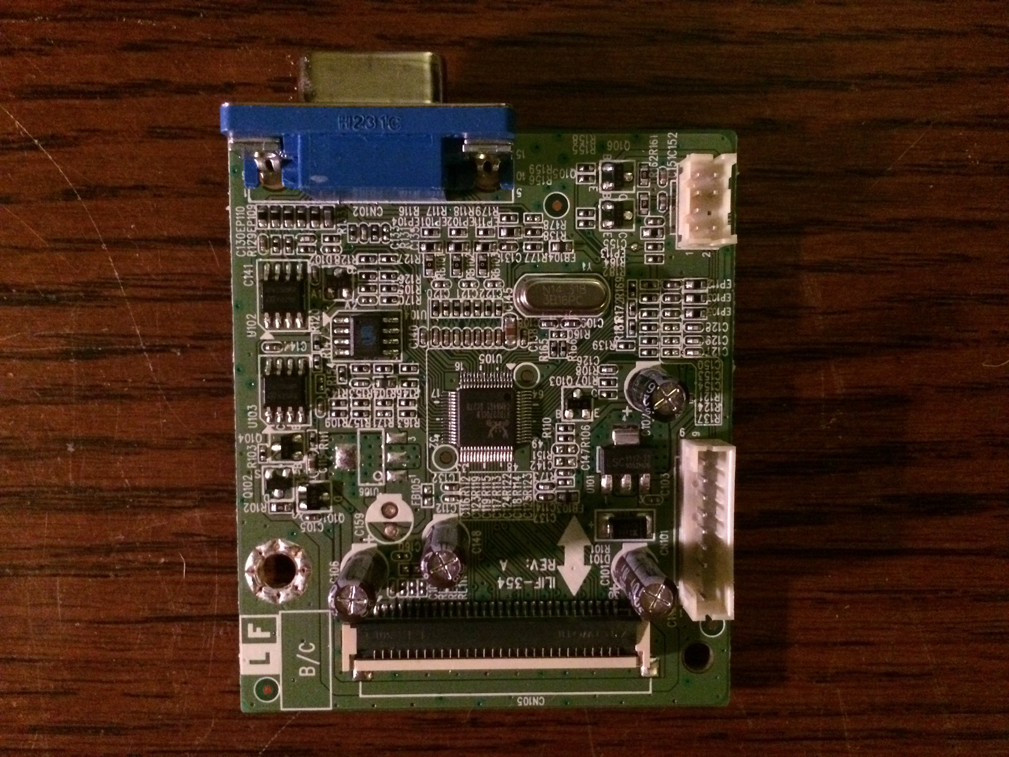
Two monitors means two controllers, thankfully they are small and draw a small amount of power.
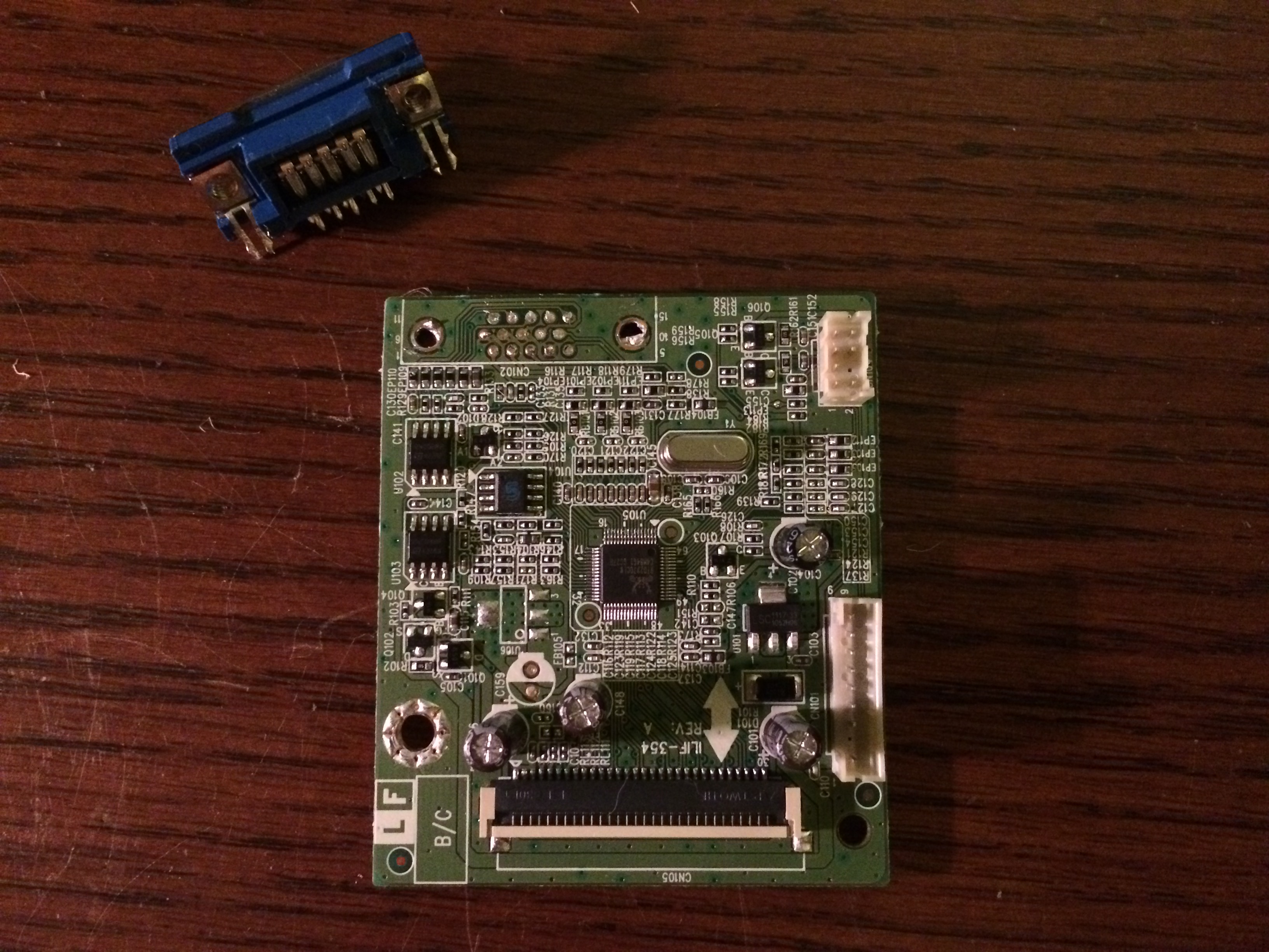
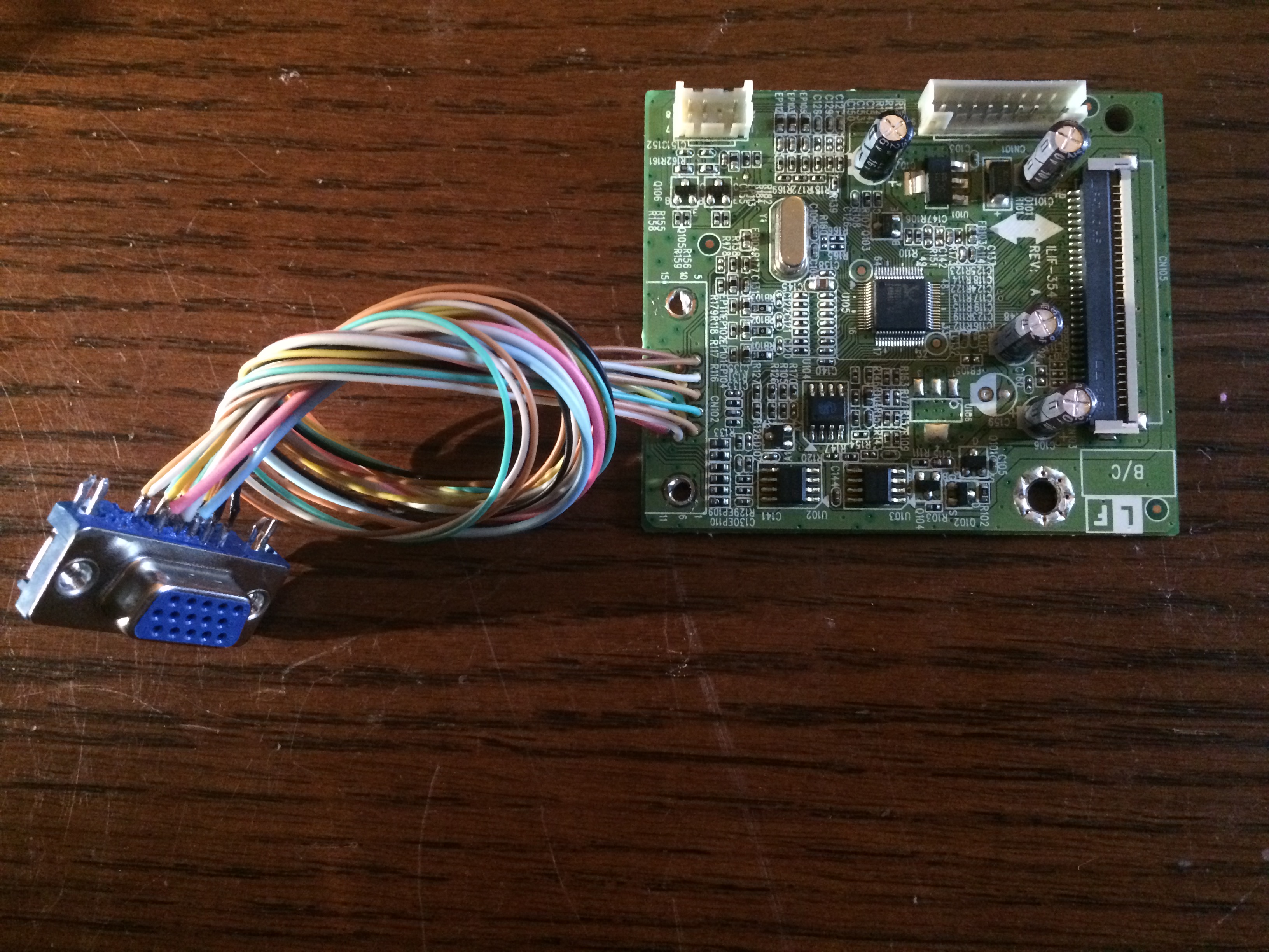
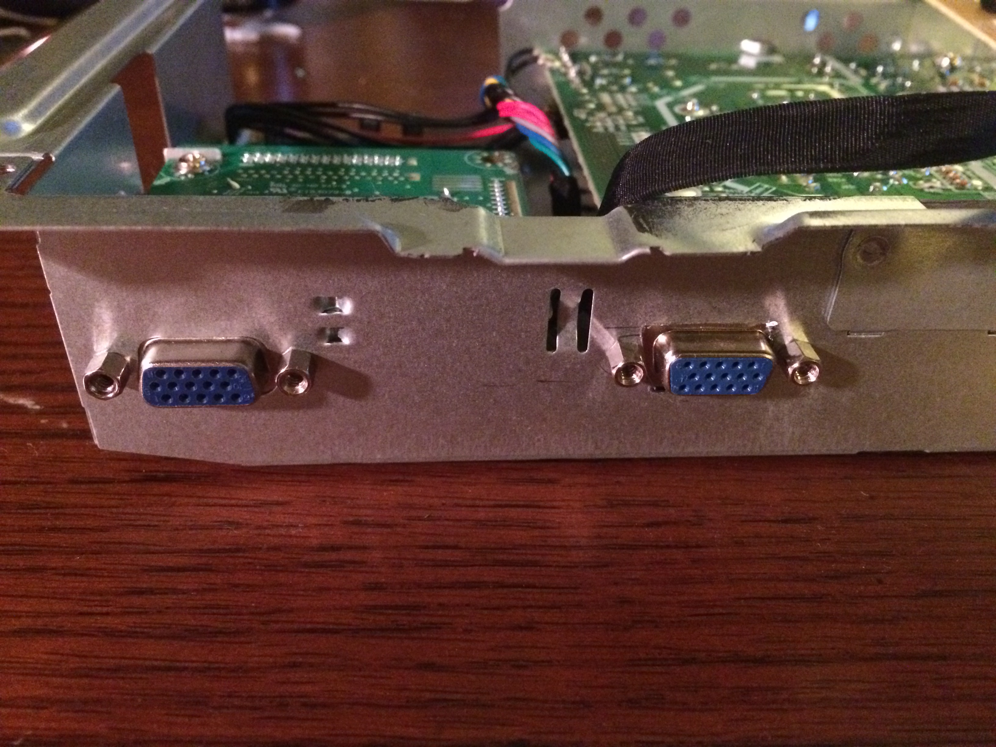
There was not a clear way to mount the second controller so that the VGA port was accessible in the back so the port was desoldered and extended.
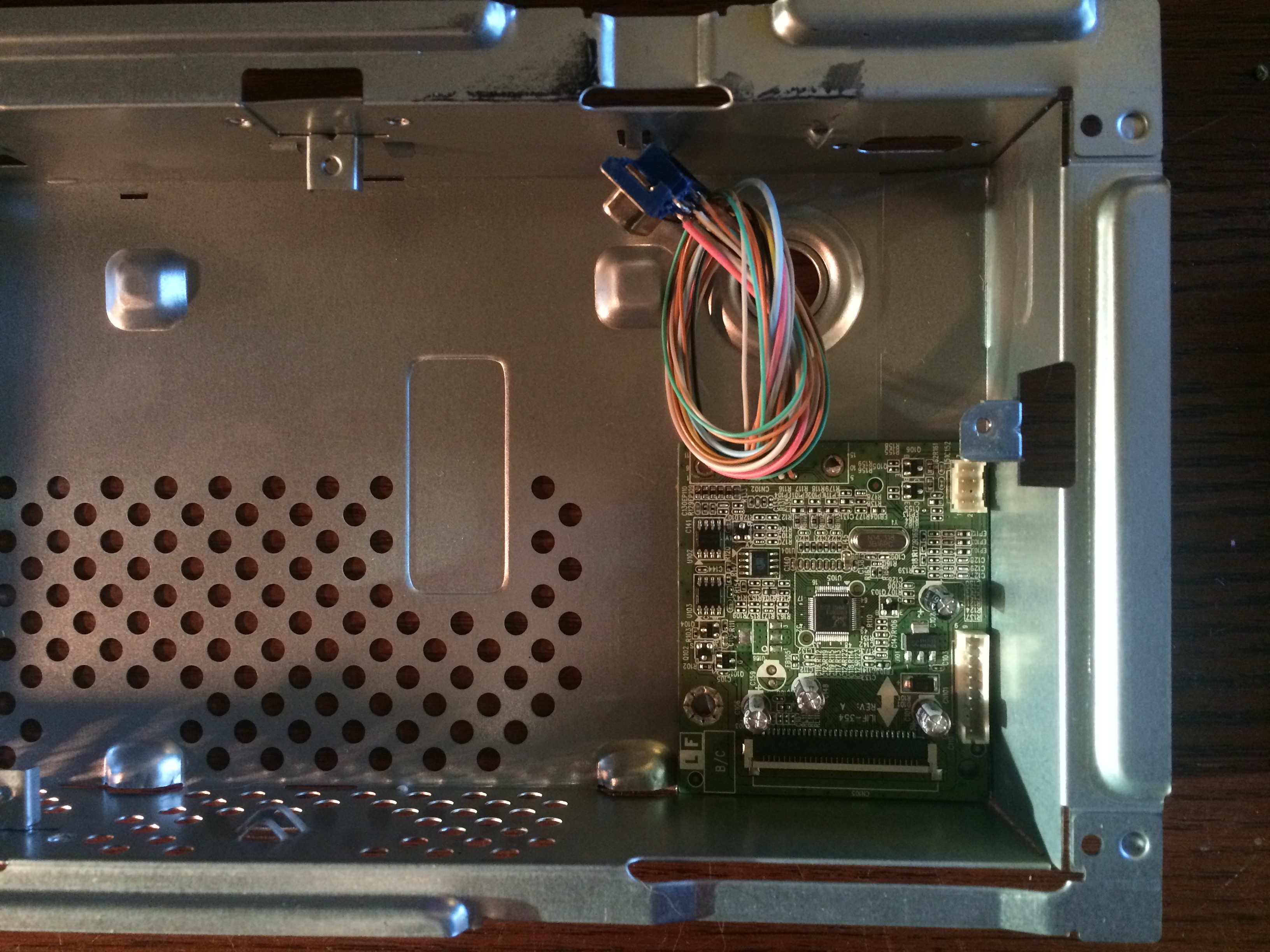

A place was found where the second controller could be mounted inside the main metal frame of the monitor and a few Dremel cuts and drilled holes later it was all mounted with the second VGA port out the back.
Putting It All Together
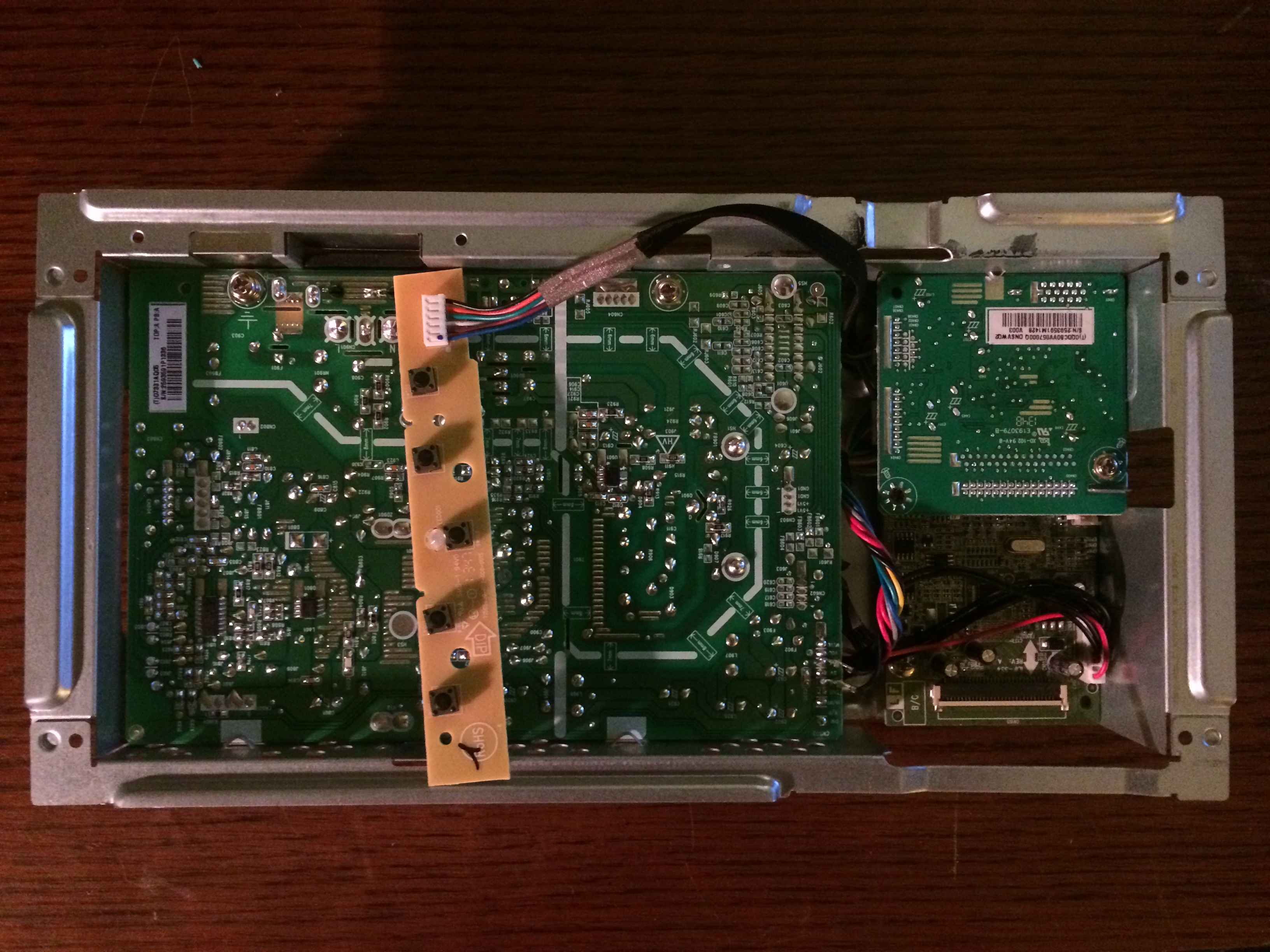
With the second controller mounted it was time to reinstall the other boards and make sure everything fit back together.
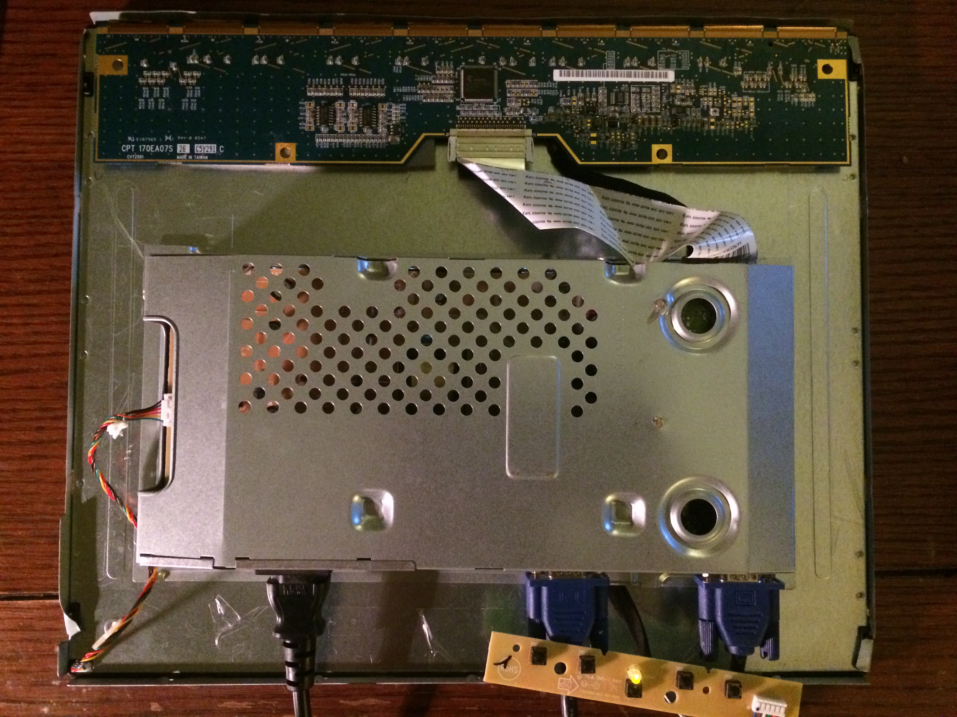

The final shot of all the internal electronics of the new double monitor and then a quick test of the effect itself. Using the actual lanyard from Google I/O I was able to see the hidden desktop icons and a control panel window that is normally hidden.
Parts and Carnage
Even being extremely careful with these panels they are still very fragile and chances are that at least one or two panels will break while trying to remove the polarizing film and then being attached. During this project a total of 5 LCD panels and 2 controllers were used, 3 of the panels being damaged in some way that prevented them from making it into the final outcome.

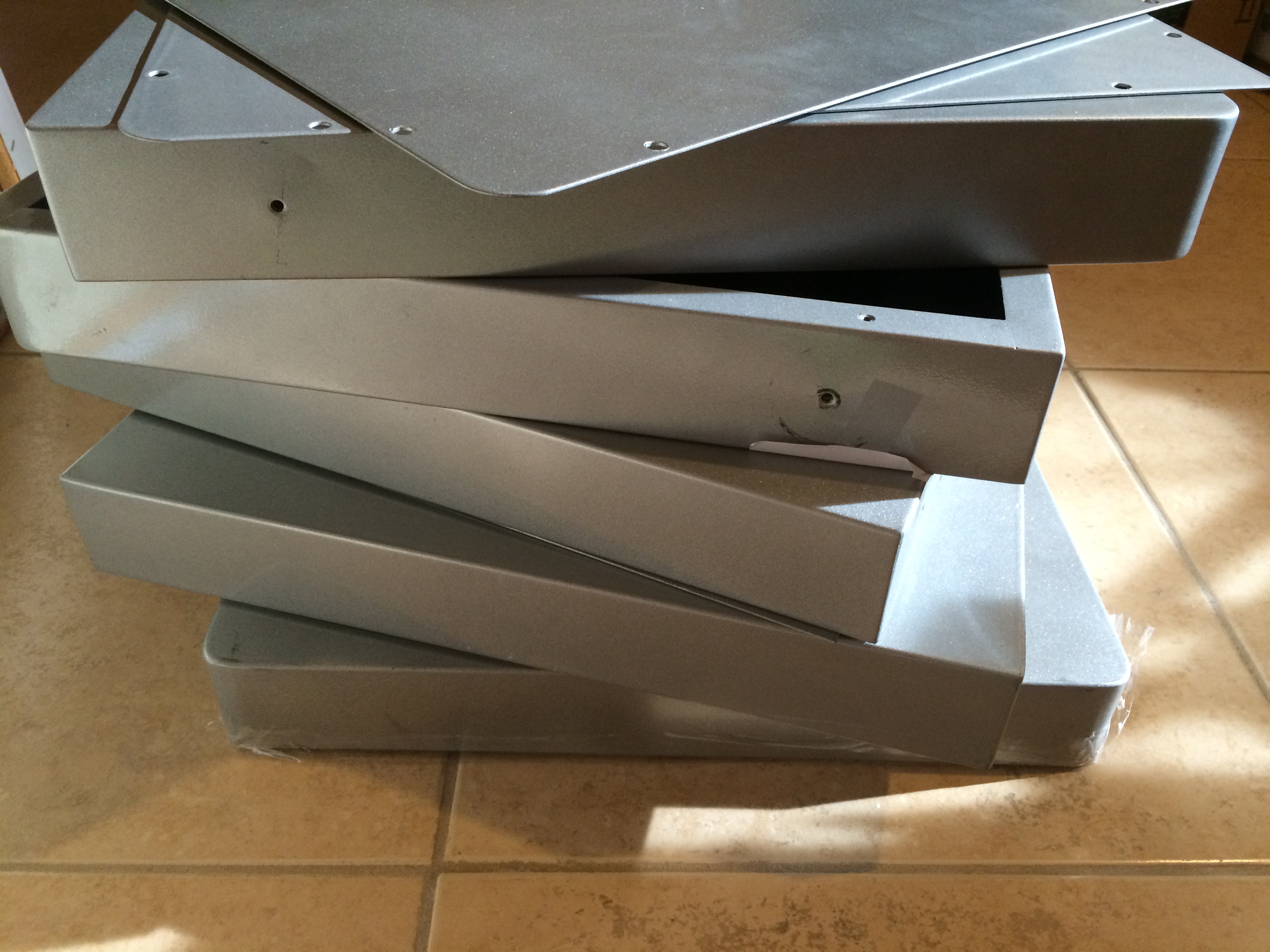
Below are the ways that three of the panels were damaged and should be used as a word of caution when trying to replicate this project.
- Heat Spots – Having recently purchased a heat gun it seemed like a good idea to warm up the polarizing film and loosen up the glue. This did help to loosen up the glue but ended up burning dark spots into the glass even at a low heat.
- Broken Ribbon – After getting through about 95% of the process of removing the gunk left over from the polarizing sheets I had the bright idea to use a Dremel and buffing wheel to remove some of the left over residue that was left after using the razor blade. A small slip and a small nick on one of the ribbons between the glass and the controller meant several lines of the display went dark.
- Cracked Glass – Using a metal spudger from an iPhone repair kit it was much easier to remove the polarizing film but about 75% of the way through removing the second sheet the glass suddenly cracked under the pressure.
It is worth noting that this isn’t the type of project I would attempt with brand new parts, all of the panels used here were surplus that had been in service for almost a decade and was destined to be thrown away. The panels were stripped from their original housings and bolted into kiosks and being VGA were of decreasing usefulness.