Description
The goal of this project was to build a wireless SNES controller that has the feel and action of the original hardware while also upgrading the interface from the SNES connector to a more modern USB connection.
Introduction
Instead of re-inventing the wireless wheel I started with a proven wireless keyboard and mouse technology. Using a single Logitech Unifying Nano Receiver it is possible to connect up to 6 devices using a single receiver. Once paired the device never needs to be synced again unless you wish to associate with a new receiver.
Starting with an unused Logitech keyboard I received with the Logitech Revue that never really took off I was able to integrate the control board inside of the SNES controller for that classic stock gaming feel.
Finished Project


The wireless SNES controller and the accompanying nano receiver.
Disassembly
No disassemble Johnny number 5.. It’s a good thing that neither the SNES controller or keyboard can talk and thus won’t complain as they are each torn asunder. This is where the feasibility of the project is determined by examining the components of the keyboard to determine if they will fit inside the SNES controller without bulging or external modification of the case.

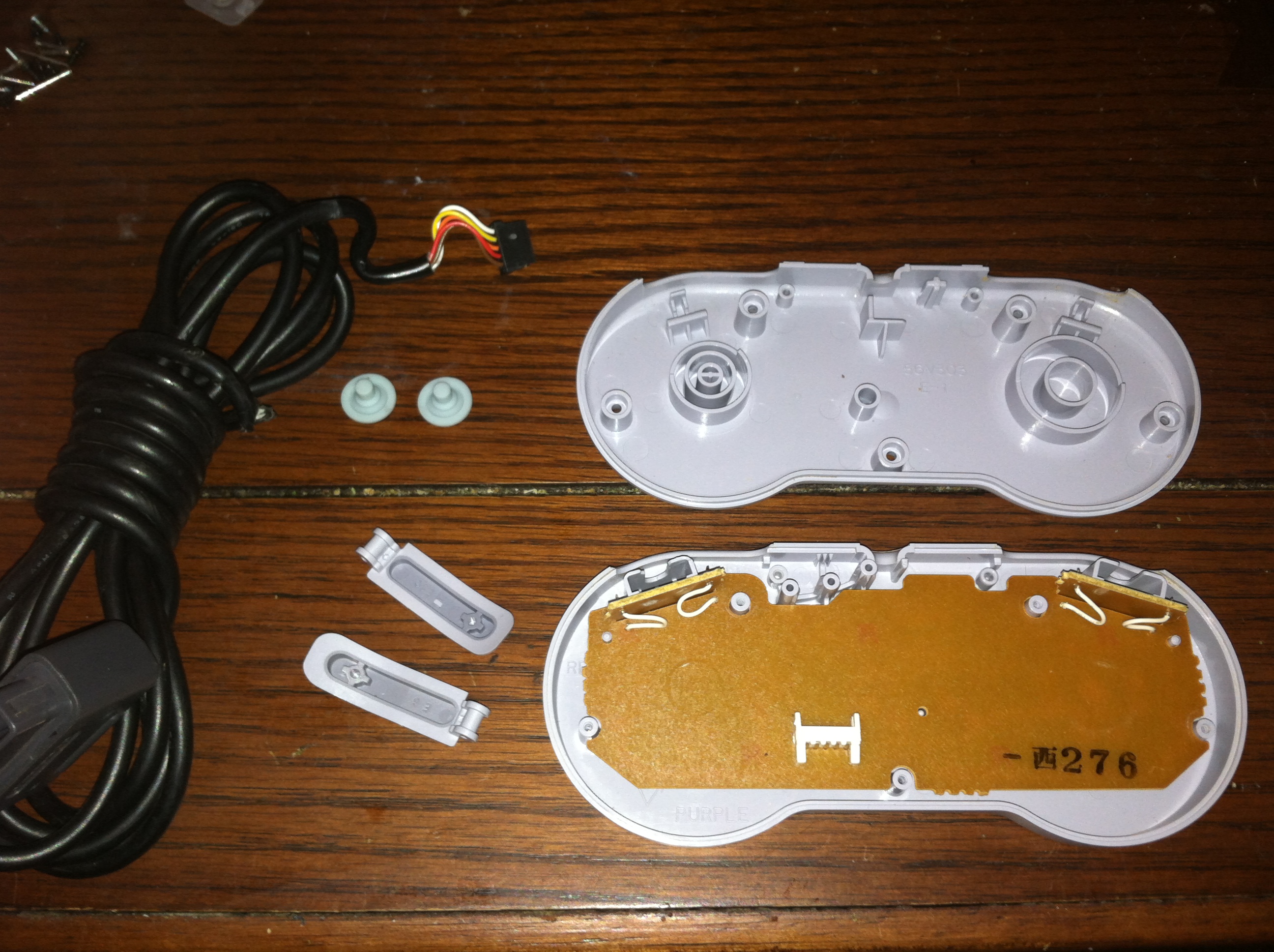
The first step was to dismantle the SNES controller and see what type of modifications will be necessary to fit the keyboard control board inside. Nintendo build everything with an extreme amount of detail and high quality plastics that still feel great to the touch and function properly nearly 23 years later.
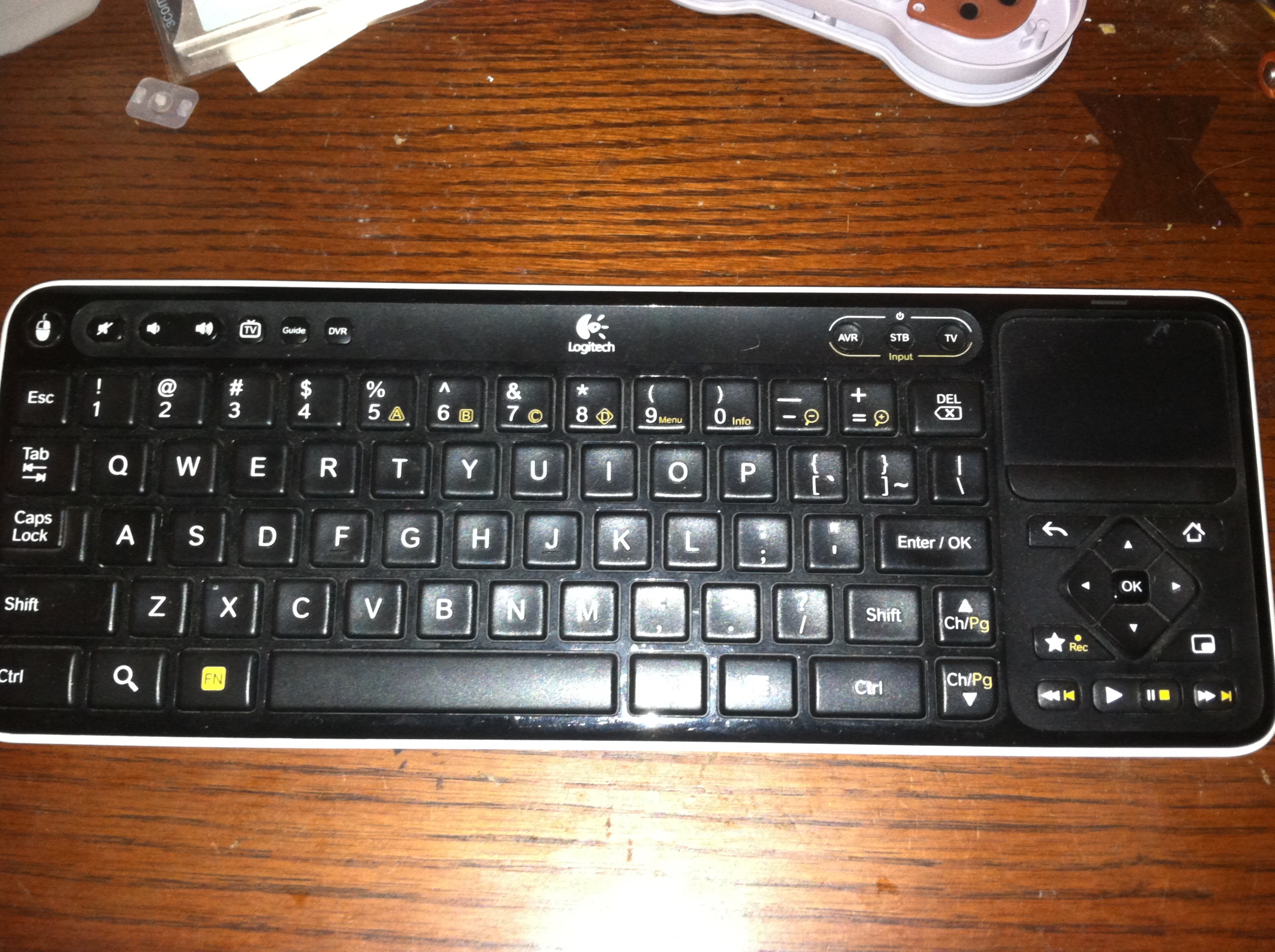
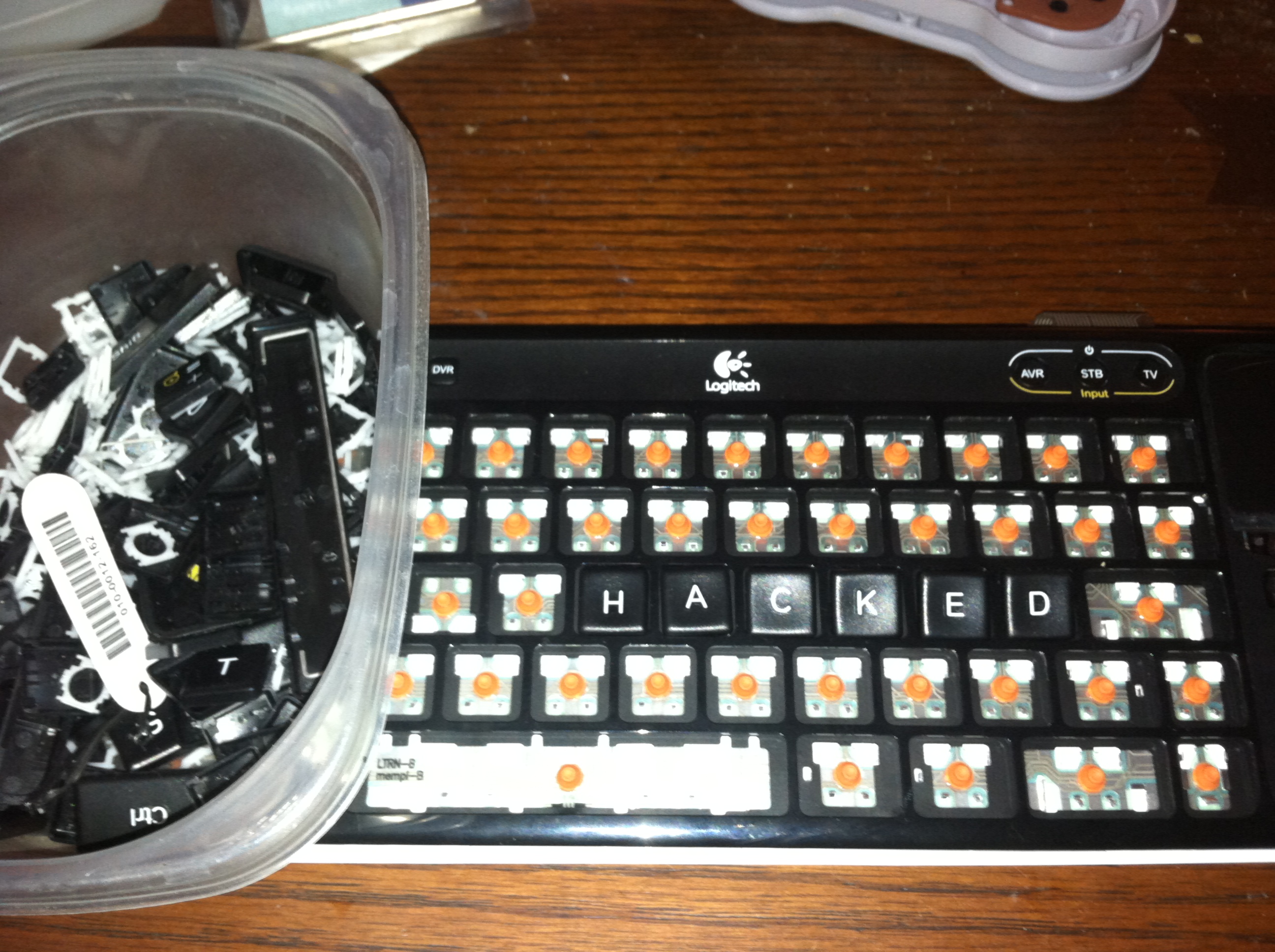
The keyboard was fairly difficult to disassemble and required that every key be removed before I could gain access to the membrane. With the membrane one could easily determine which keys on the keyboard map to which pins on the control board. A typical keyboard can not read all the keys at once either due to multiplexing, charlieplexing, etc.. By choosing keys which map to distinct pins on the control board the theory is that all or most of the buttons on the controller can be pressed at once without cross-talk.
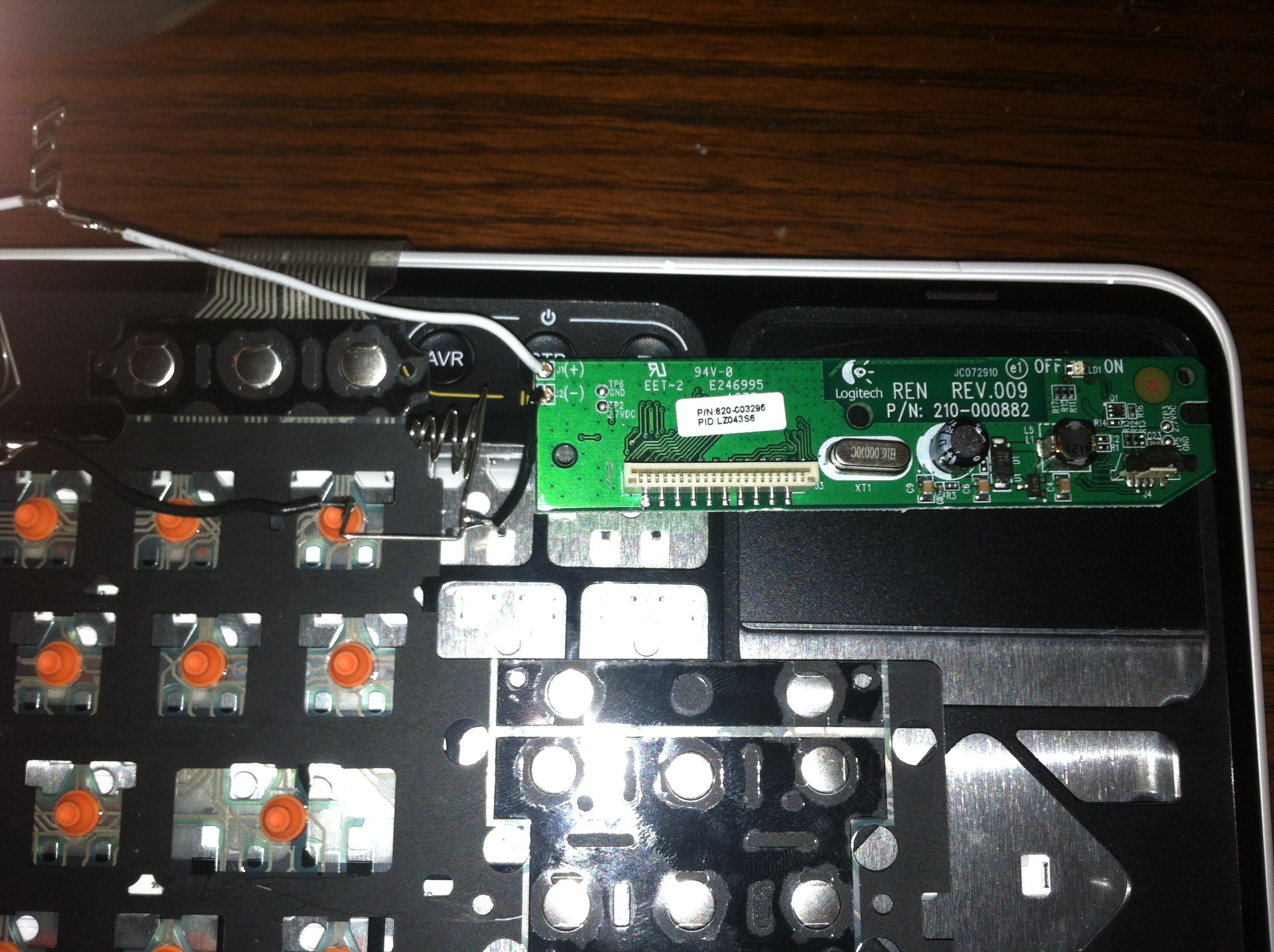
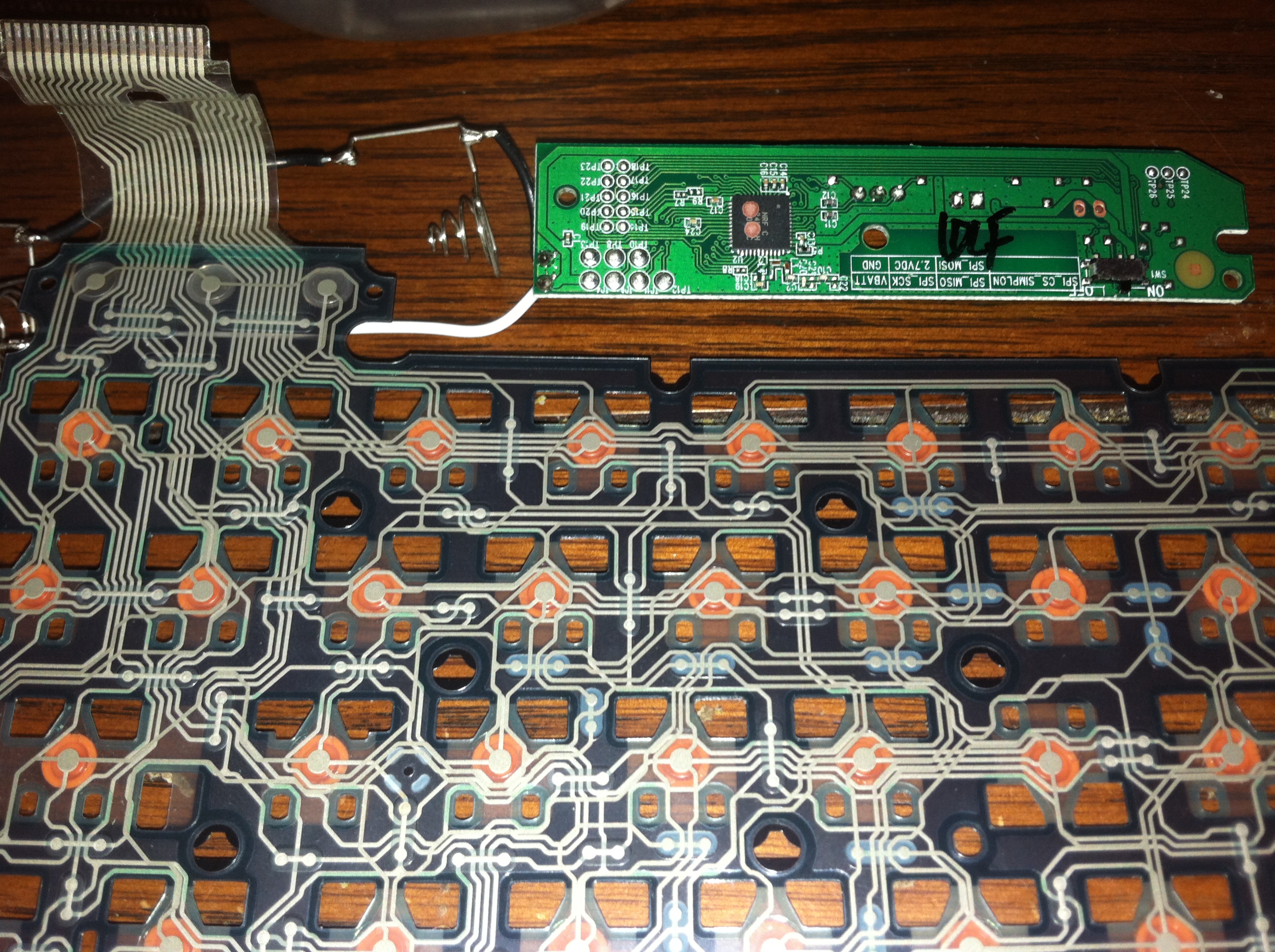
It was at this point I realized that the membrane was too complicated to map by simply following the traces. Once I had the control board disconnected I started by soldering a wire to the first pin on the connector and with notepad and/or a key mapping utility I mapped out which keys I could use to the pin combo on the control board. Wanting to stay within the “normal” keyboard keys such as A-Z, 0-9, and basic symbols such as ,[]’; etc meant it would take some effort to find unique pin combos that will work.
Attach and Interface the Control Board
With our mappings and other details figured out for the moment we can start to attach the control board and interface the keyboard membrane connector with the 12 total buttons of the SNES controller.
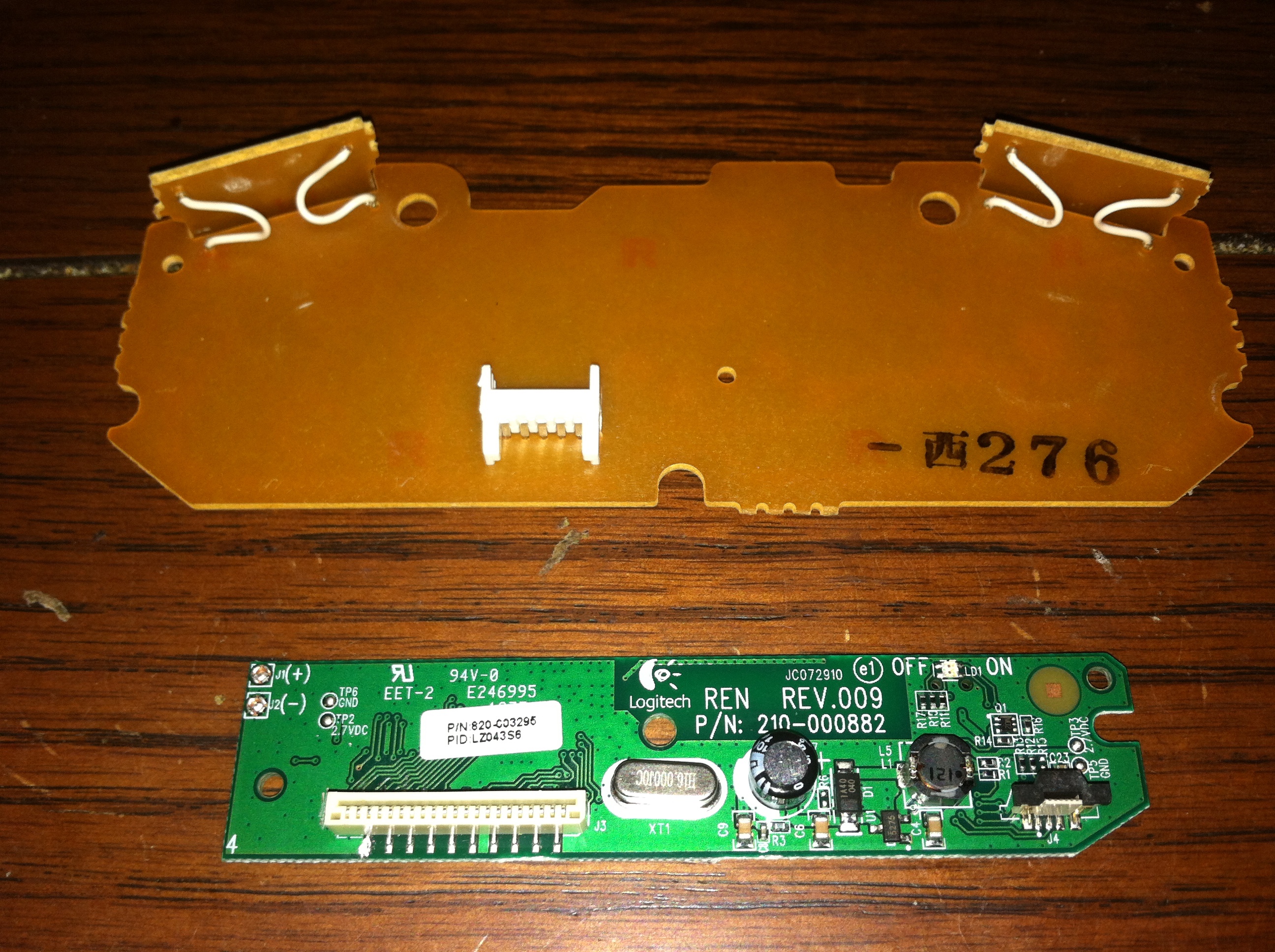
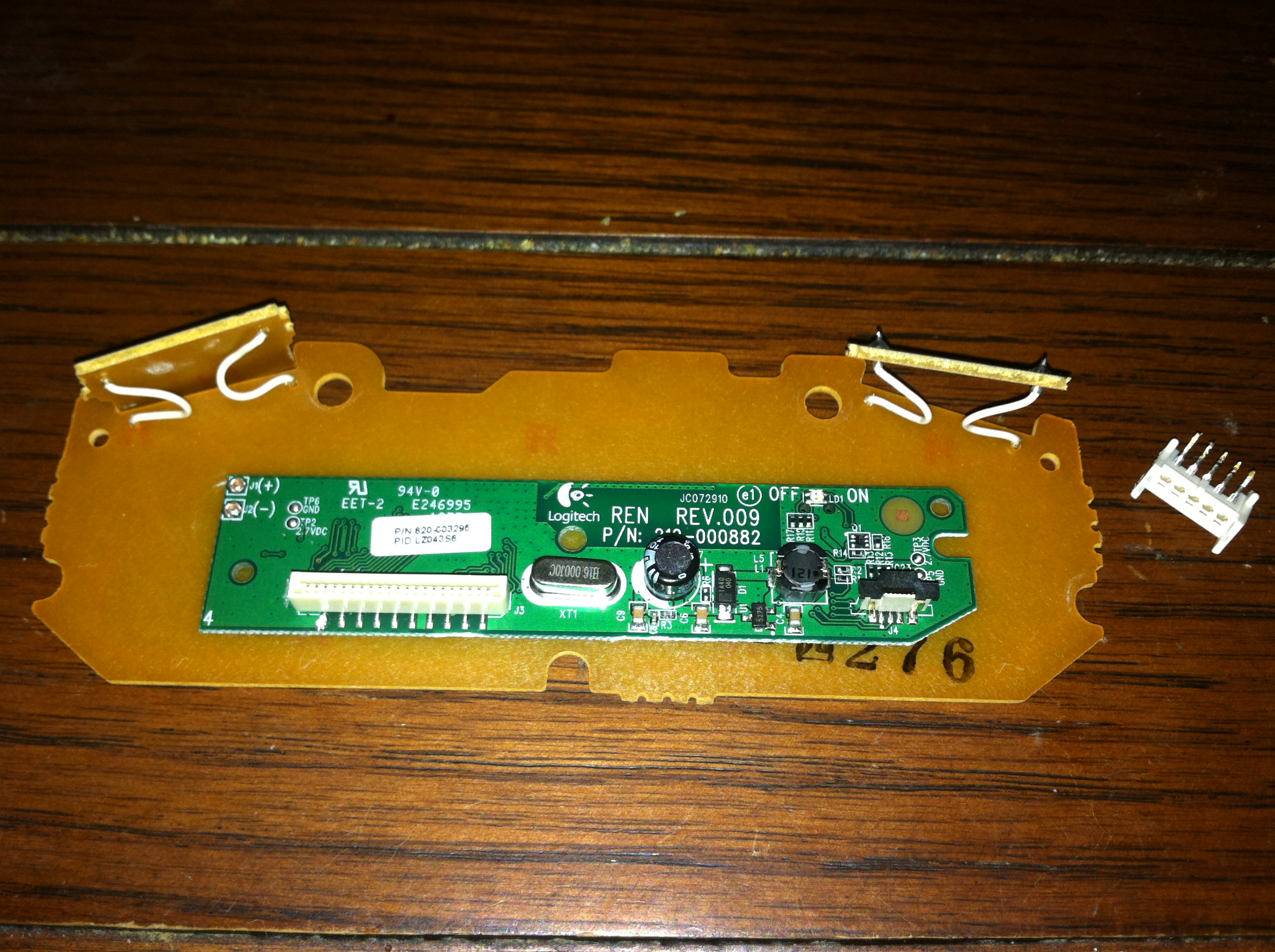
It seemed easiest to attach the keyboard control board to the back of the SNES gamepad board. In this way both boards can be removed as a single unit including the wires and eliminate the need to create a modular connector between the two. When designing a DIY project like this it is important to consider the amount of times you are likely to take the project apart to make further enhancements or modifications and ensure that wires aren’t breaking loose etc..
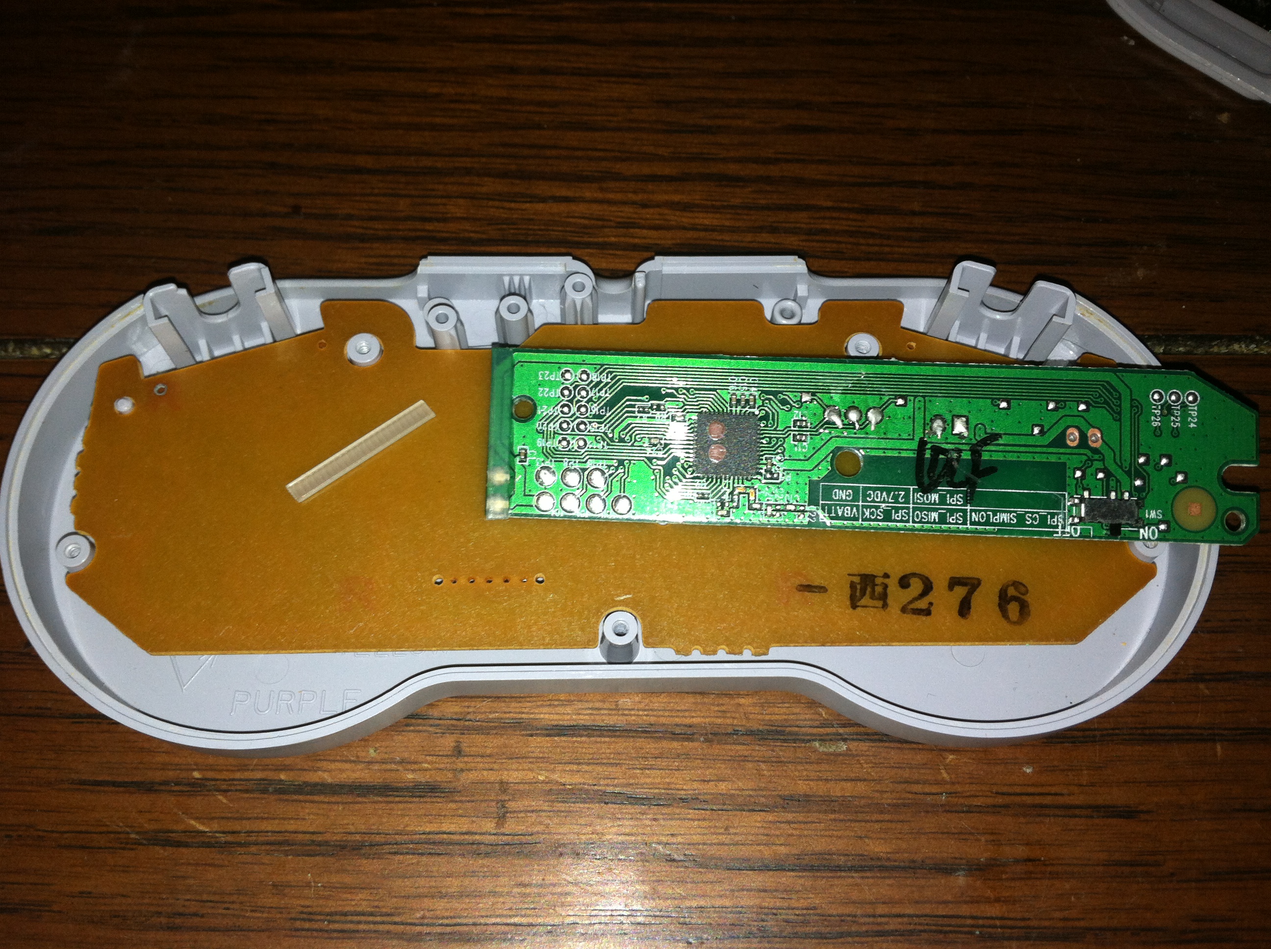
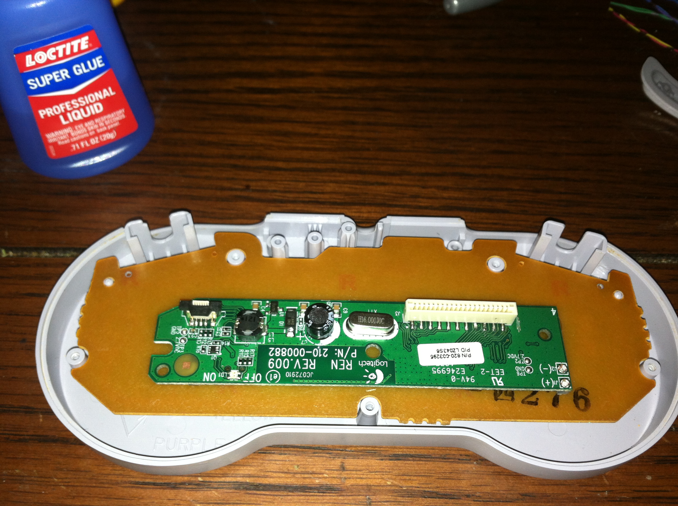
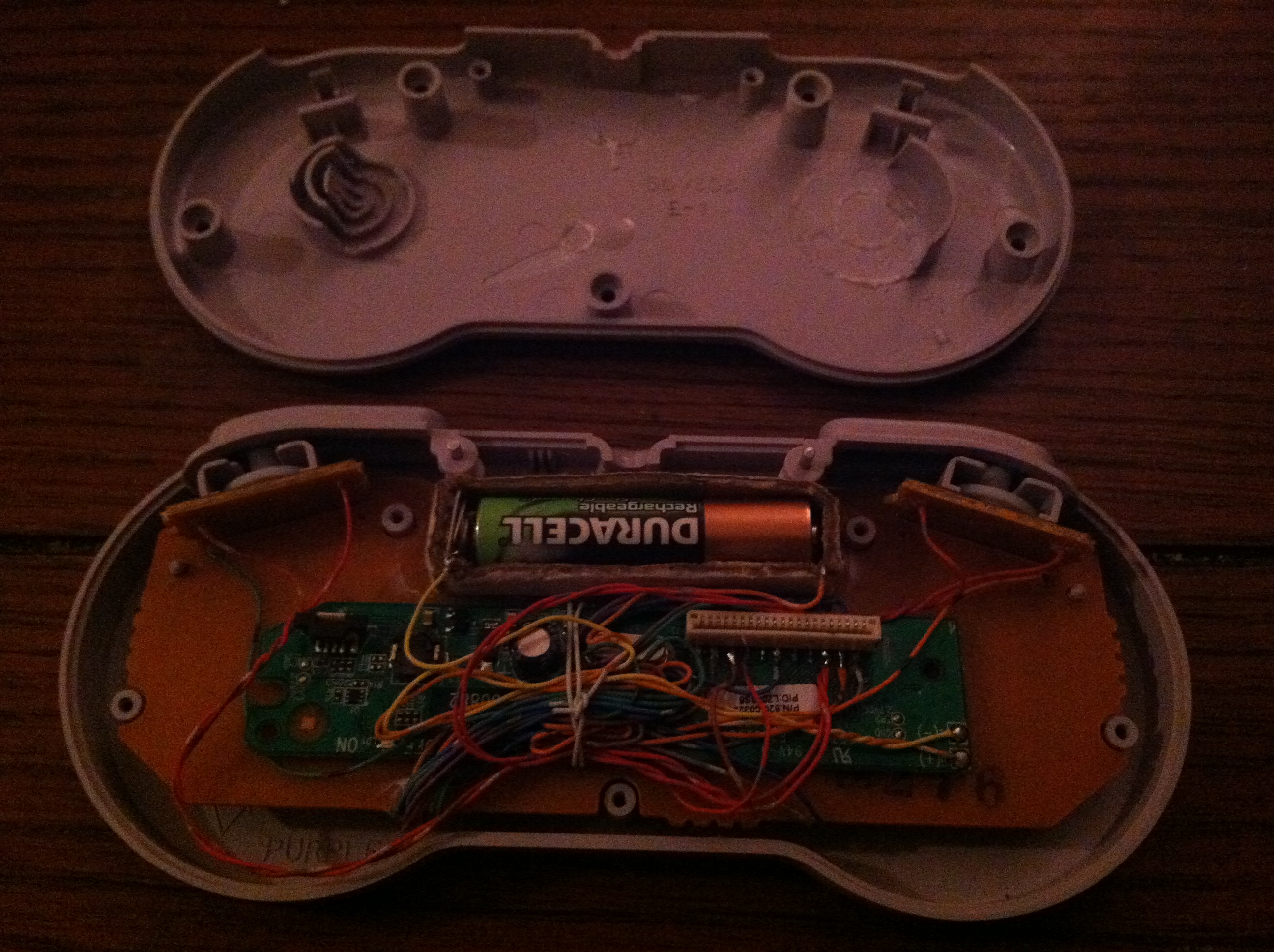
A mounting location is chosen and care taken to ensure screw holes and other parts aren’t obstructed. Using some scraps left over from a Zip-Tie small strips are cut that will be glued to the control board and then glued to the back of the controller’s board to give the surface mount components on the bottom room to breathe.
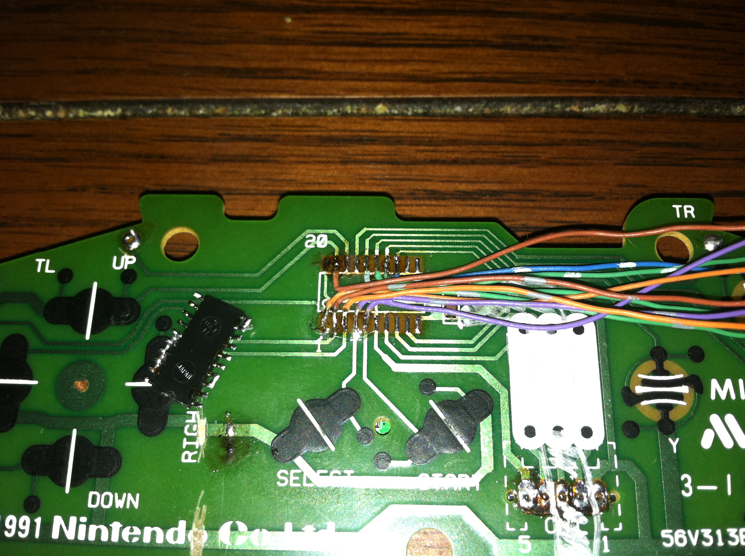
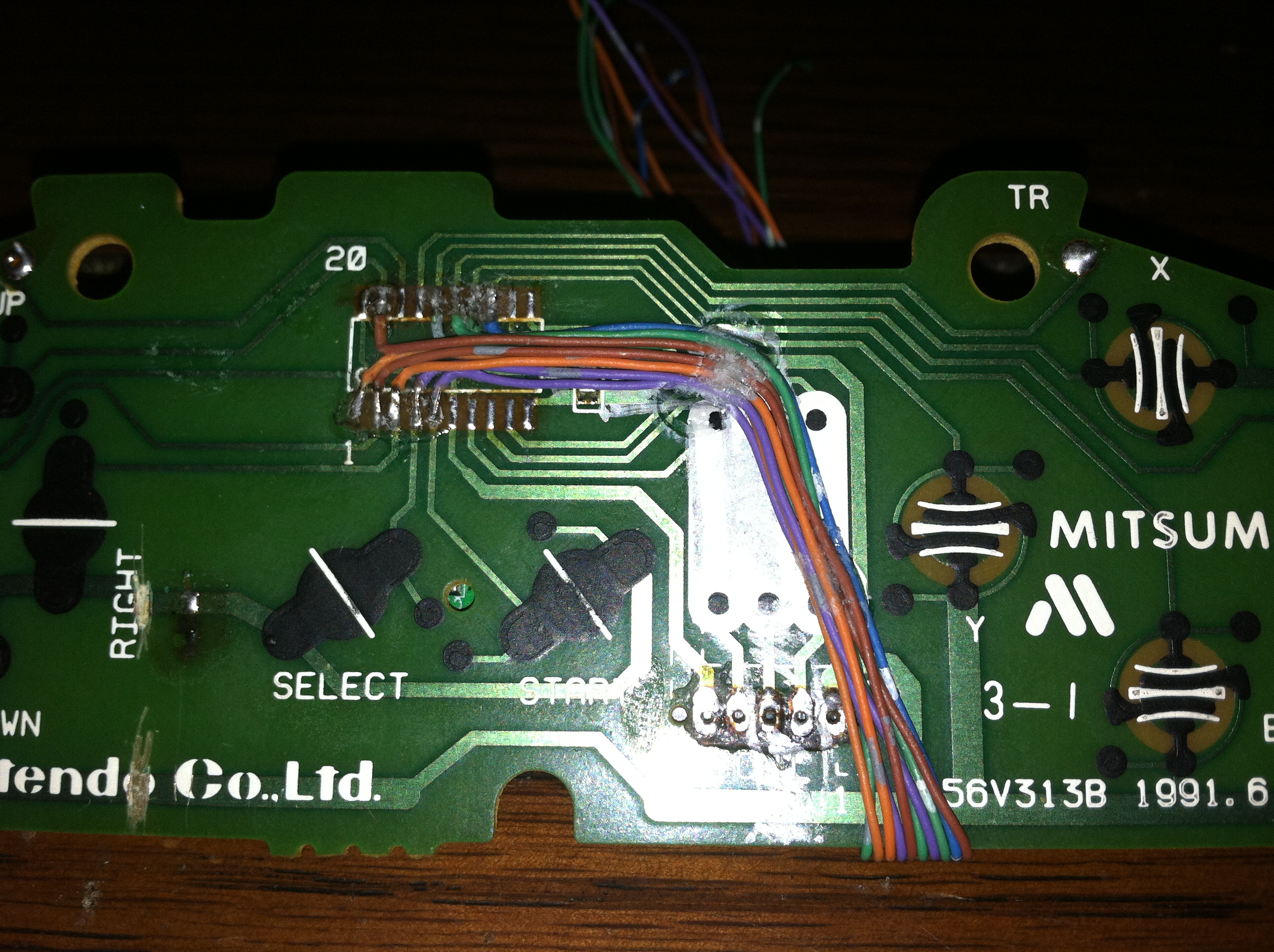
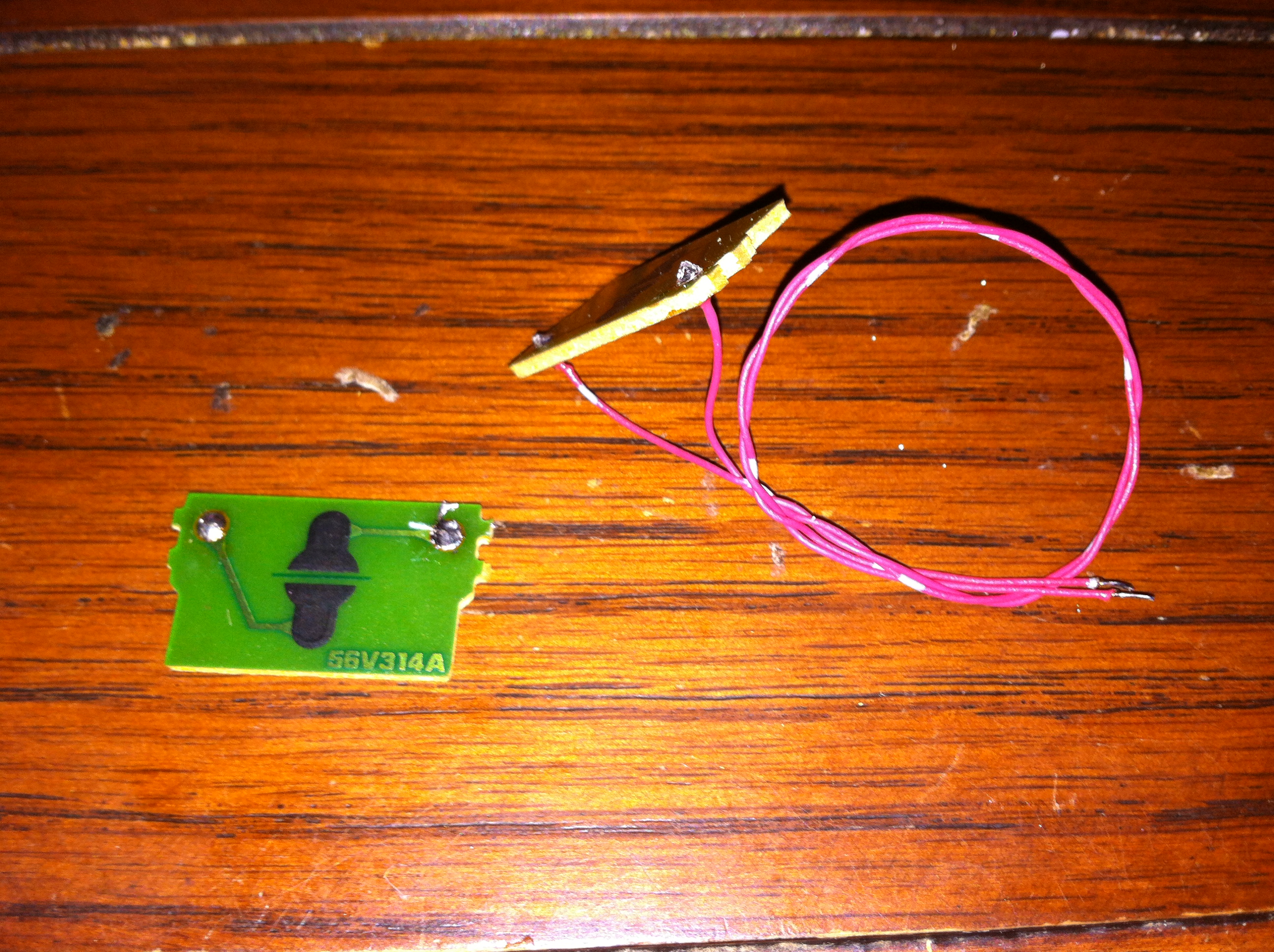
With the boards mated together it was now time to start interfacing the two together. Handily all the buttons on the controller each have their own pin on the controller’s interface chip, with the chip removed from the board I can prevent any interference with the chip and easily access all the solder pads. Although there are 12 buttons only 10 wires are soldered here since the left and right triggers are on their own boards it makes more sense to connect these directly to the keyboard control board.
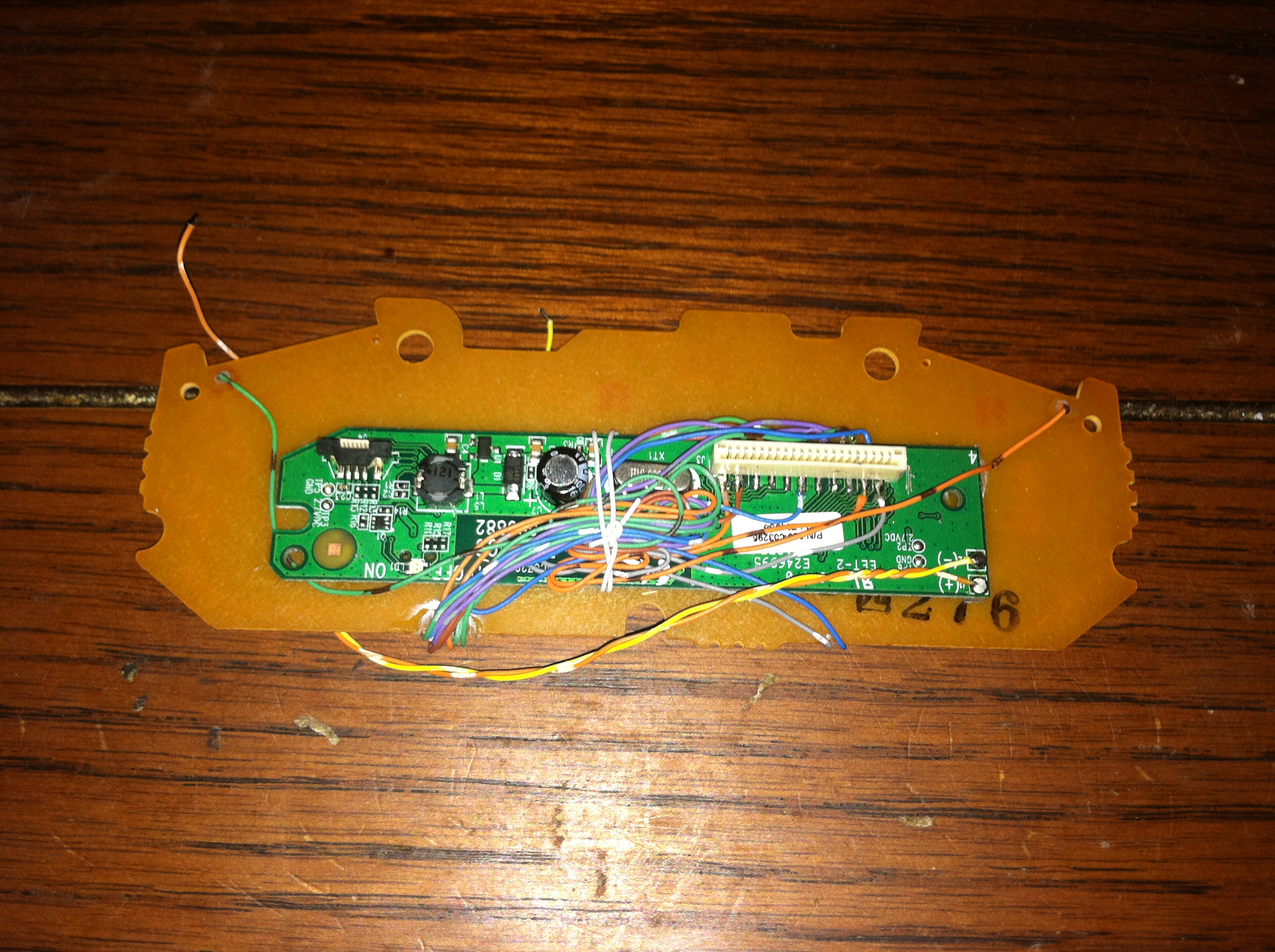

Now that all the wires are connected to the front are routed to the back they are then soldered to their respective pins on the keyboard control PCB. The grounds are broken between the Direction Pad, A/B/X/Y Buttons, and Start/Select Buttons and wired to the common pins on the keyboard controller in much the same way the membrane works in the actual keyboard. Lastly the wires are tied down with a loose piece of wire and keeps the boards and their wires contained while also leaving it open to future changes by not glueing the wires down at this stage.
Powering the device
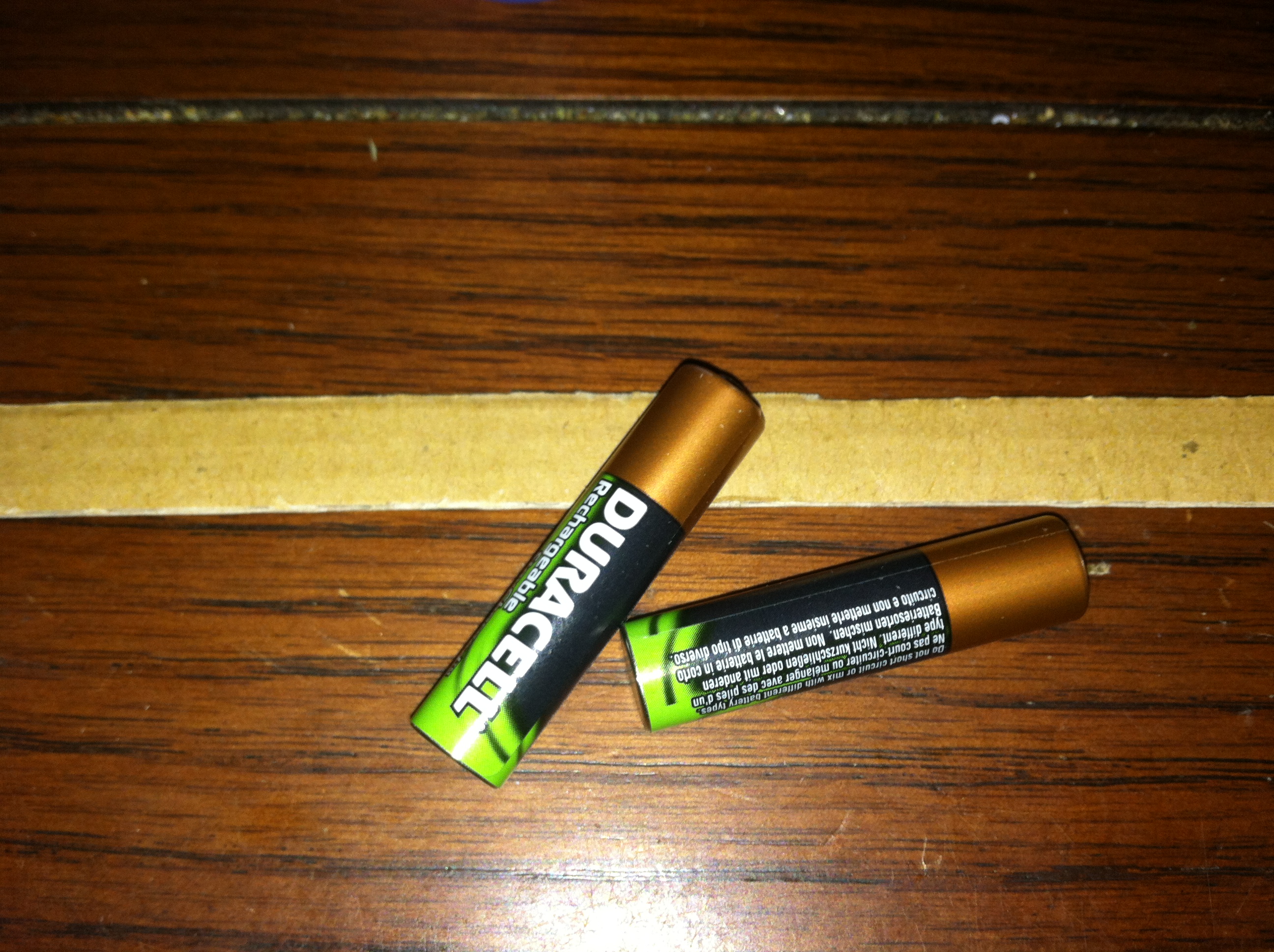
Often the hardest part of a project can be in the details of the power interface for your project. The original keyboard was powered by two AA batteries in parallel meaning the control board runs from a measly 1.5 volts. This made choosing a battery both difficult and at the same time rather easy.
By trying to fit various batteries from my parts bin I eventually realized that the space available in the controller easily fitted a AAA battery. The original keyboard ran for over a year on two AA batteries and by using a single high capacity rechargeable AAA battery the controller should run for 6 months or more.
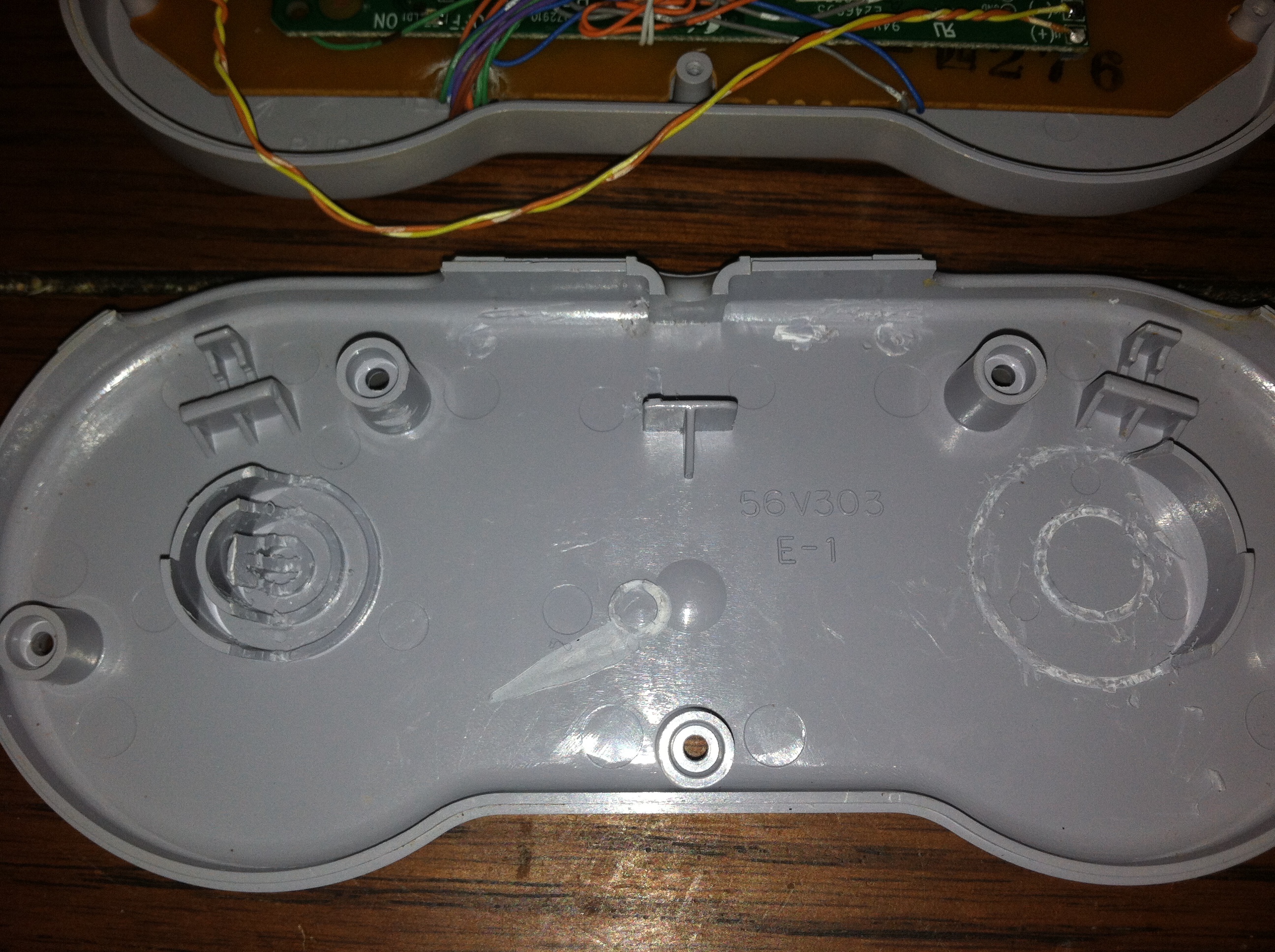
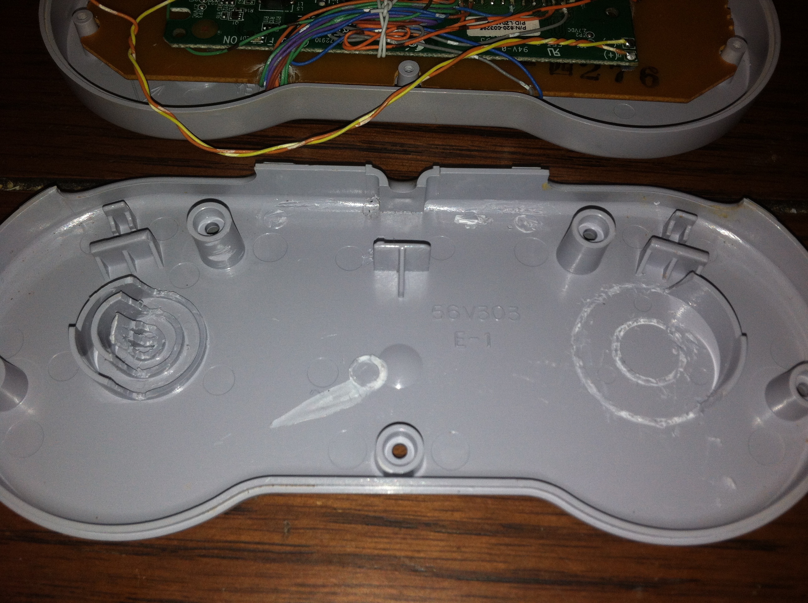
First some of the plastic is removed from the back plate of the SNES controller to leave room for both the control board and space for the battery to fit. There are no cut-outs on the back of the controller to preserve the original feel of the controller. This does present a problem with changing the battery but I would much rather remove 5 screws to take off the back plate versus an ugly cut-out that ruins the feel of the mod.
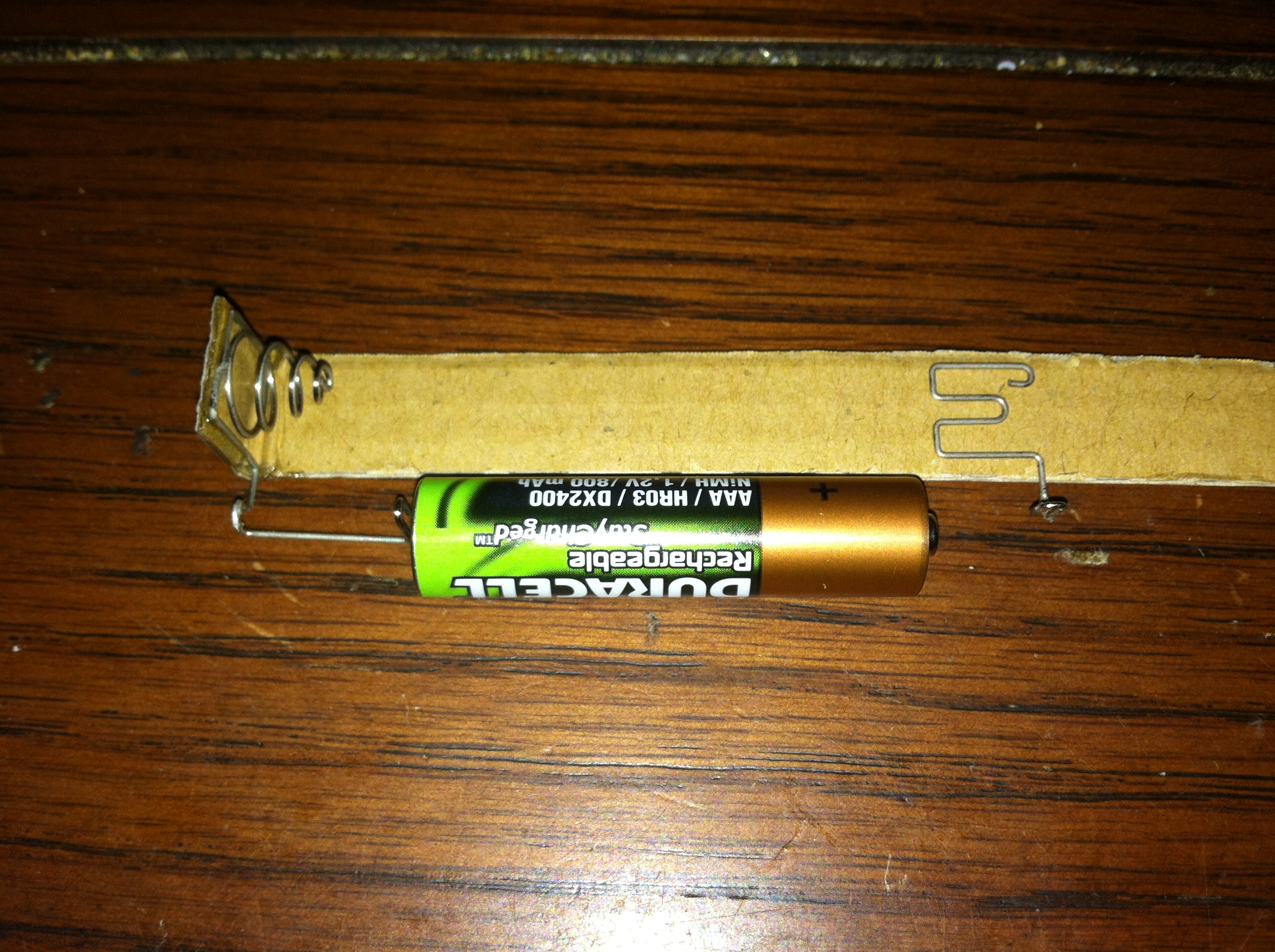
Choosing a battery like a AA or AAA requires some sort of holder with a spring that will hold the battery in place and make the appropriate electrical connection. Without a ready built holder and with a bit of imagination a usable holder can be constructed out of cardboard and Loctite professional superglue, I dare anyone to find a better superglue. First a small strip is cut that is about the same width as the diameter of the AAA battery. Spring contacts were taken from the original keyboard body since the footprint of the metal was closer to the size of a AAA than the AA batteries the keyboard used.
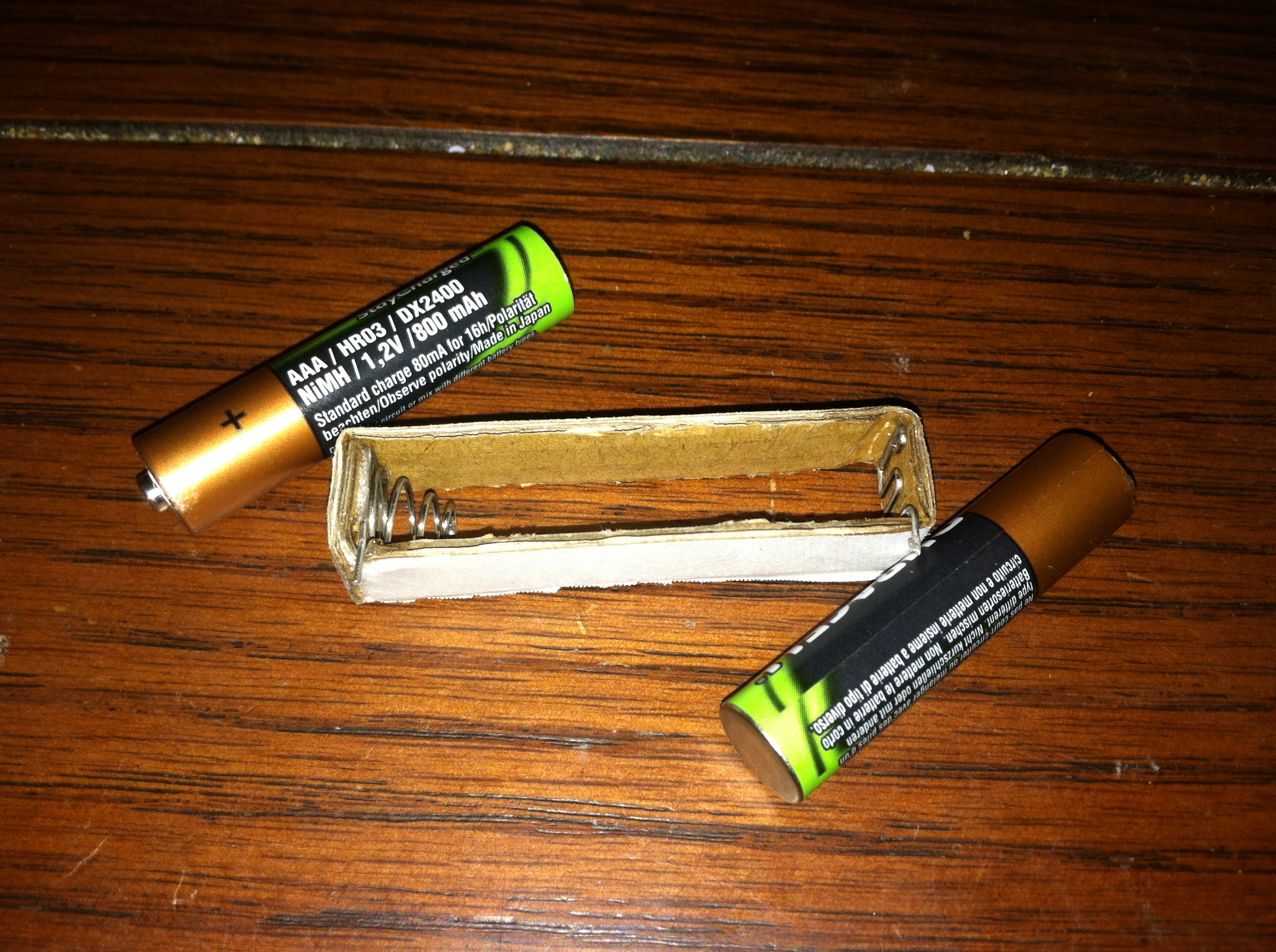
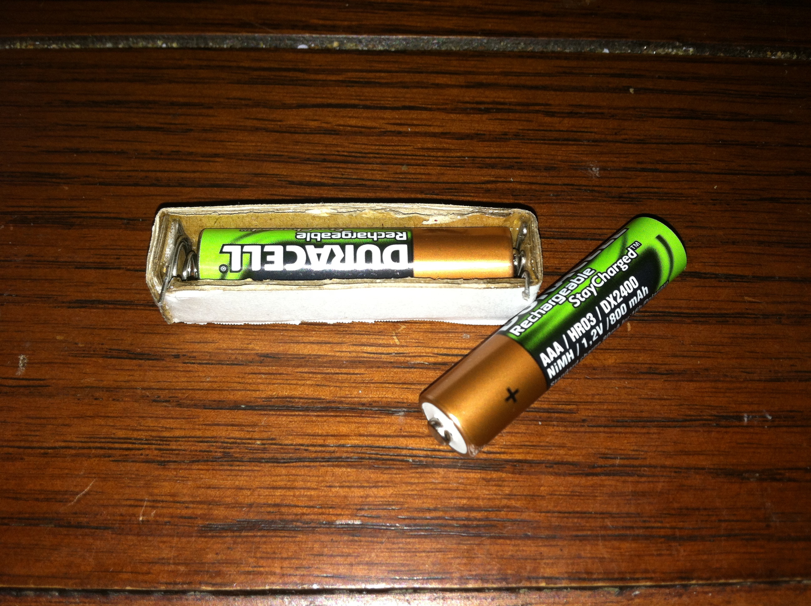
A few bends and some glue later we have a sturdy AAA battery holder that can be custom designed and trimmed to fit within the body of the controller. Small tabs poke out from either side of the holder to connect to the power wires for the keyboard control board.
Bringing it all together
With the key aspects of the mod all worked out it came time to finally bring all the components together and begin the first of several test fits before attaching each item permanently with superglue.
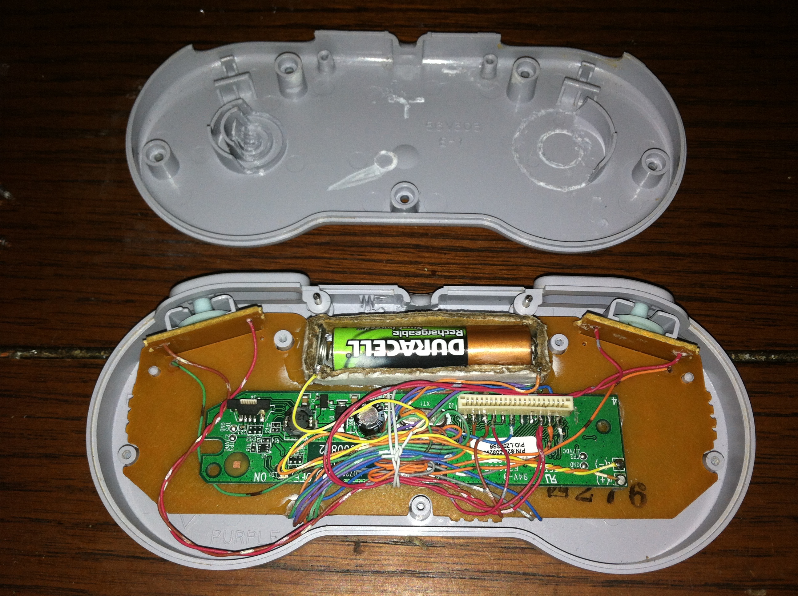
Lastly the trigger buttons were soldered up and wires interfaced to the keyboard control board. Using a tab of superglue at the part where the wire comes out of the back of the trigger button boards ensures that even when disassembled multiple times that the wires wont ever break loose of their solder contacts. The battery compartment is attached and wires soldered to the power connections of the keyboard control board.
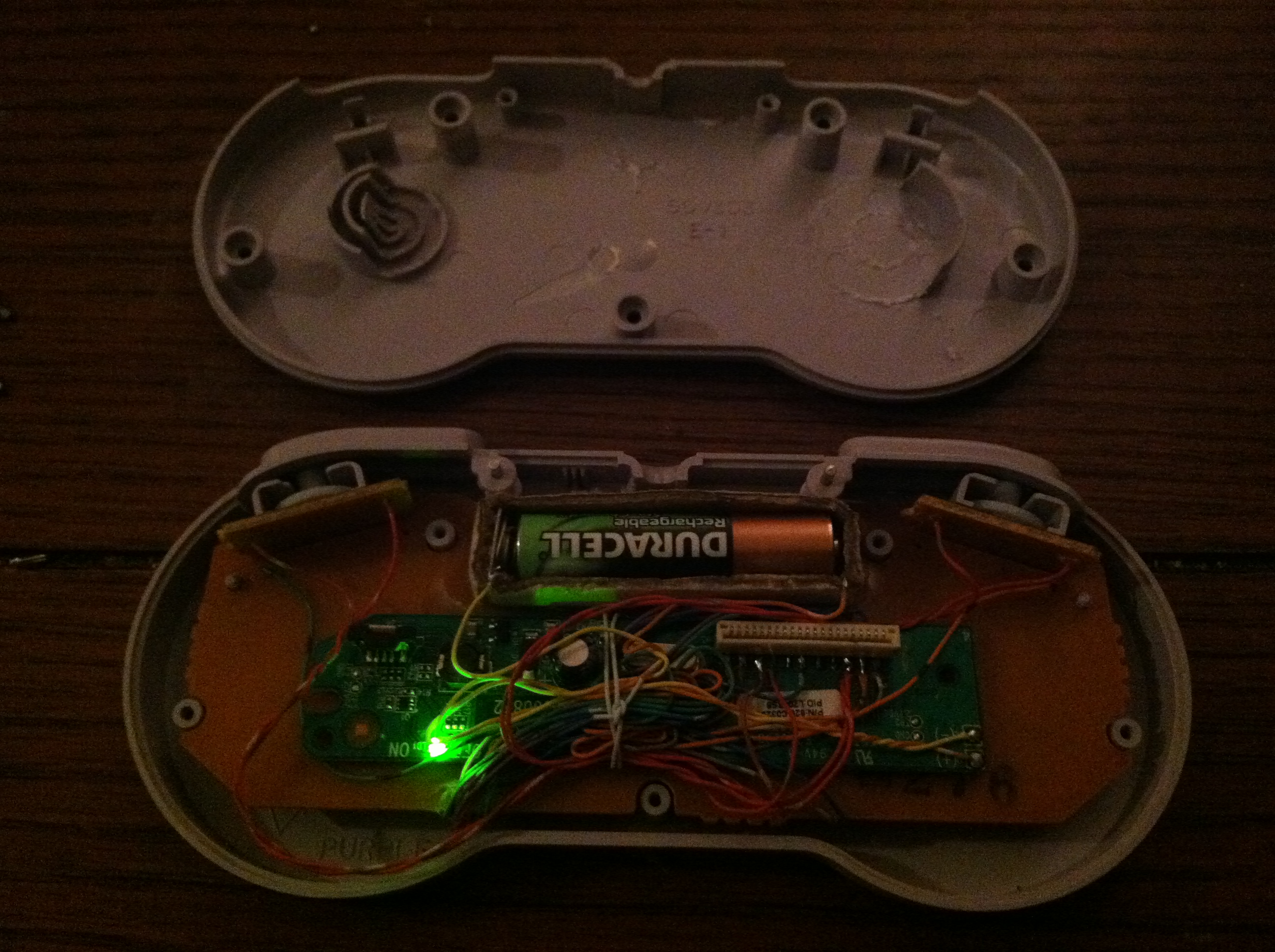
Here is a shot showing the little light that comes on when power is connected to the keyboard control board and also shows all the parts in their final arrangement before the back plate is reattached.
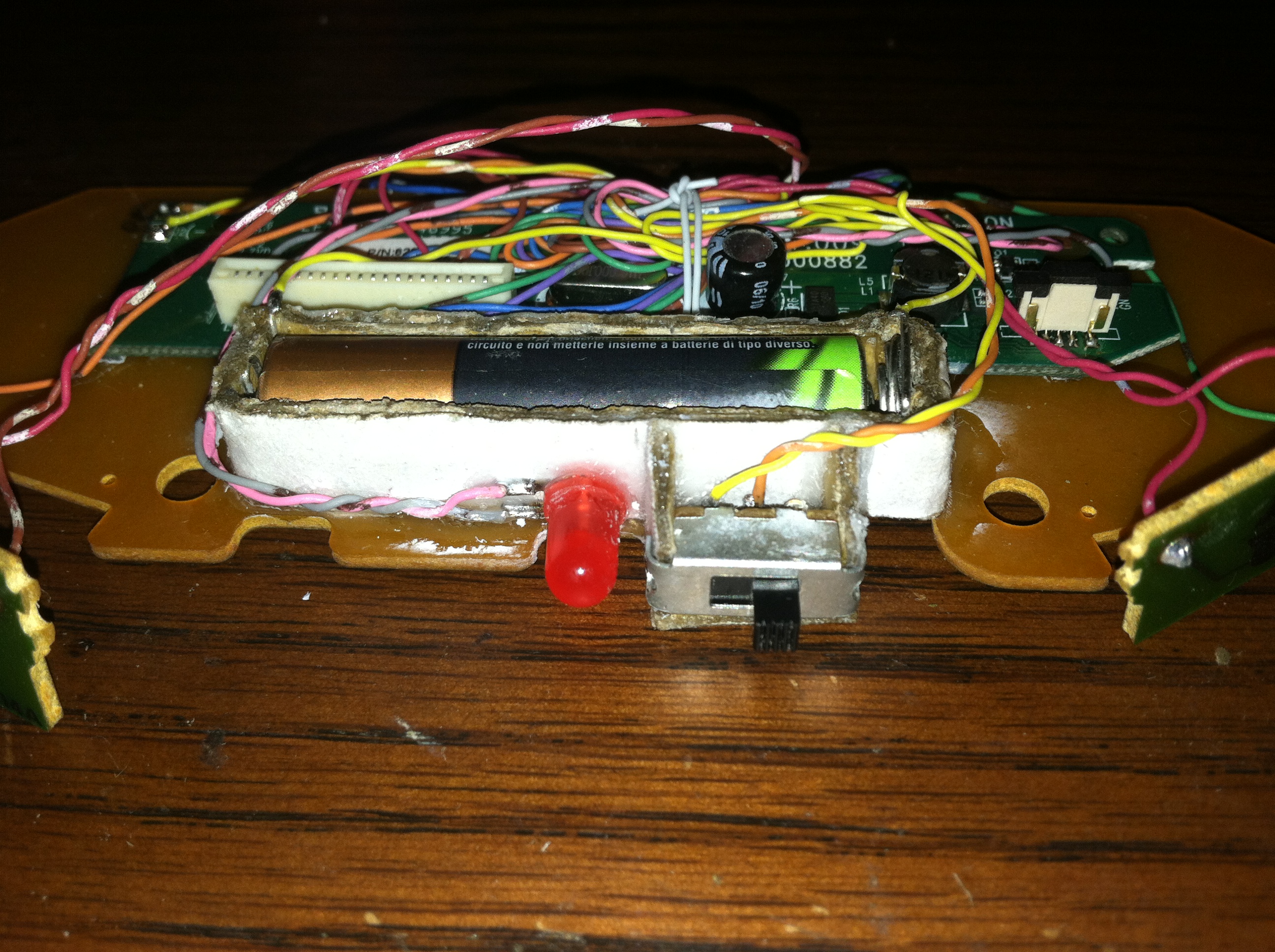

Ensuring that the battery lasts as long as possible between charges a power switch is was added and marks the only external modification to the controller case. Additionally a power LED was glued in place to occupy the hole previously used by the controller’s cord. Everything is attached to the main board assembly with the plastics being completely independent of all electronics.

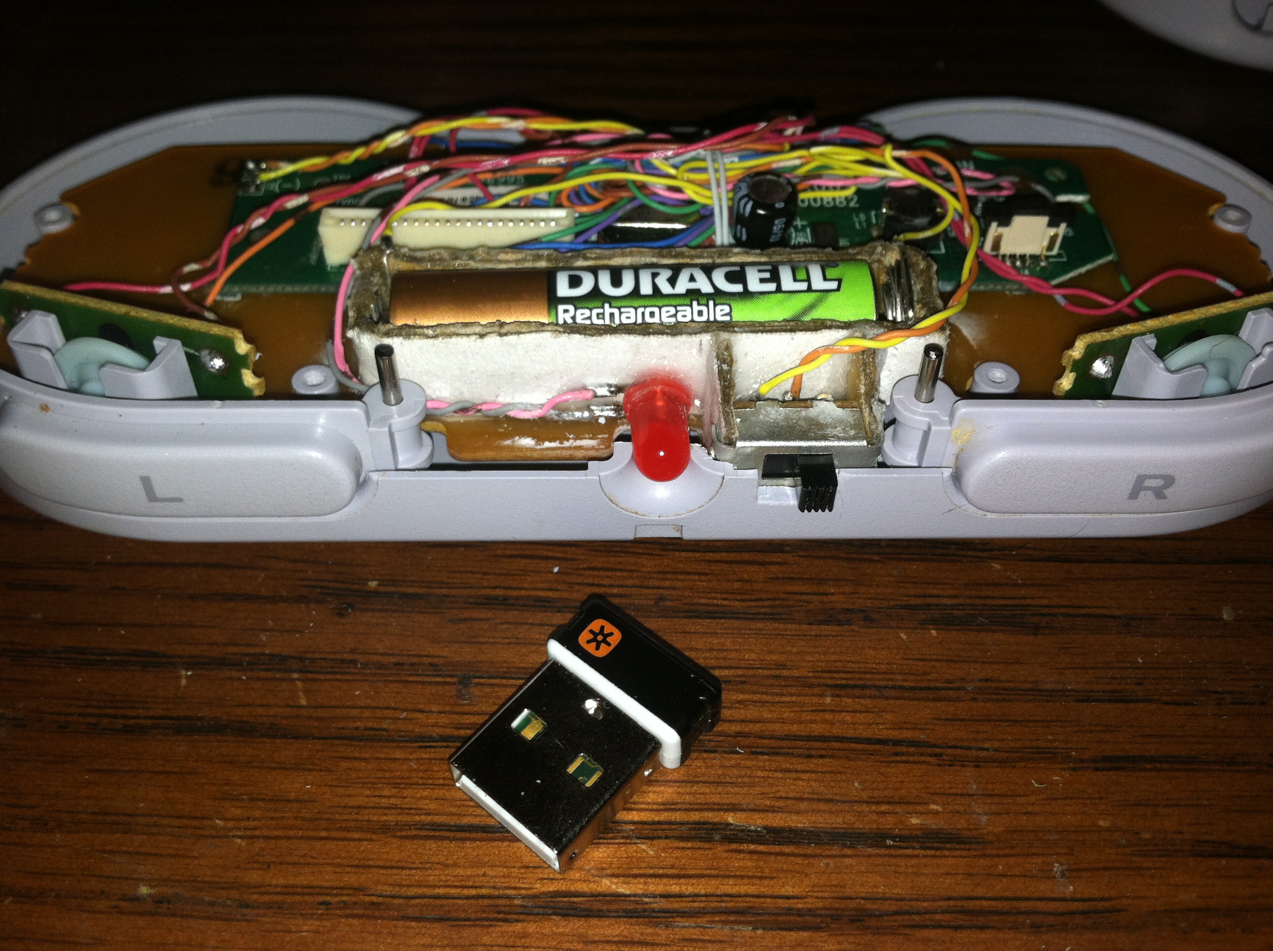
Finally you can see the way all the parts fit together in the projects completed form.
Keyboard Pinout
The below pinout was derived by soldering a single wire to a given pad on the keyboard’s controller and then touching that wire to all the remaining pins while monitoring the key presses in either notepad or a keyboard mapping utility. The pinout is incomplete but should suffice for determining some pins that can be used with the SNES or other controller.