Description
Introduction
The below images are from a guide by Xin Feng FixUp.net that at the time of this writing was no longer available. I have added my own comments and text that reflect my own experiences performing this mod on a few different Libretto 100ct units.
Finished Project
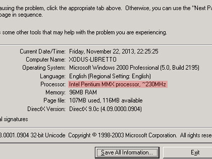
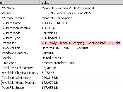
Below are screenshots with the relevant information highlighted obtained from using the DXDiag window and also the System Information utility. Each provides slightly different information about CPU and RAM.
Overclocking
First the entire motherboard needs to be removed from the laptop’s shell, thankfully this is relatively easy and fully comes apart by taking out about 10 screws that hold the two halves of the shell together. Once apart the area we are interested in is located underneath the PCMCIA sockets, these come off of the motherboard by removing 4 screws. Lastly peel back the black anti-static plastic and locate the area around the part labelled RM1, near the center of the area underneath the black plastic.

Once the area is located the specific points of interest are 6 solder points two of which come shorted or jumped by a surface mount component labelled “0” which means it has no resistance or capacitance making it simply a jumper. Generally speaking a Libretto 100ct is capable of running at either 233mhz or 266mhz. The Libretto is functionally identical to the 100ct with the difference being it comes overclocked to 233mhz by default. Unfortunately I don’t have pictures of a 110ct to confirm if this is performed in the same area as this mod.
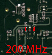
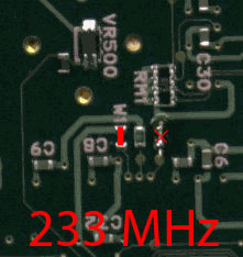
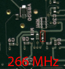
In my experience running the 100ct at 266mhz proves unstable in the long run, unfortunately due to the lack of information I am unable to find the method of over-volting the processor slightly (a common overclocking technique) to support the increased power draw. Thankfully the Libretto 100ct seems to run at 233mhz without a single issue whatsoever and is likely the reason Toshiba decided to run the 110ct at that same clock speed. Simply drop a bit of solder between the two pads in the photos above, I used a single strand of some multi-strand wire I had laying around from a previous project, anything thin and copper will work great.